Harley Davidson Panhead. Service manual (1948-1957 Rigid) - page 13


  Index      Harley Davidson     Harley Davidson Panhead. Service manual (1948-1957 Rigid)


Search            copyright infringement  


Content      ..     11      12      13      14     ..


Harley Davidson Panhead. Service manual (1948-1957 Rigid) - page 13
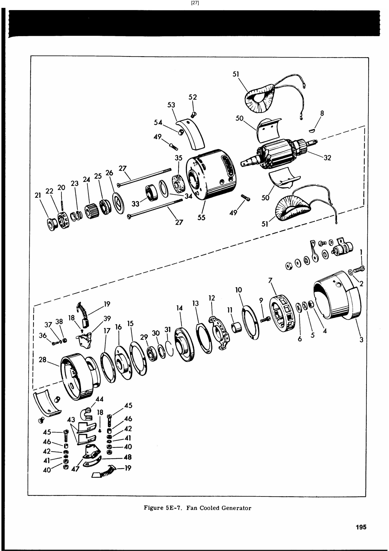


There is no need to disassemble brush holders (39 and 47) from frame end unless test proves the positive holder is shorted, or unless they are badly bent or broken. If removal is necessary, turn out negative brush holder screws (36) and terminal screw nuts (40) to free all parts.
Do not remove pole shoe screws unless necessary to replace pole shoes or field coils. If necessary, turn out pole shoe screws (49) several turns, then tap on heads to loosen pole shoes (50) from keyed slots in frame before turning screws completely out.

Air intake shields (53) may be removed at any time convenient during the disassembly procedure.

CLEANING, INSPECTION AND REPAIR

Clean all parts except gaskets, felt grease retainer, armature field coils and brushes in cleaning solvent and blow dry with compressed air. Wipe armature, field coil and brushes clean with cloth dampened in white gas and blow dry with compressed air.

Examine all parts carefully for wear. Give close attention to condition of insulators, armature windings, field coil wrapping and surfaces of pole shoes nearest armature.

If play can be detected in ball bearings, replace them. Pack bearings, liberally with "Grease-All" grease before assembly of parts.

ASSEMBLING GENERATOR

Assemble generator in approximate order of disassembly. Install field coils in frame. Insert armature and assemble the felt retainer, spring ring and bearing. Use arbor press to push bearing in place.

Assemble brush holders to frame end and slip frame end in place over frame. If frame end is a tight fit, it may be drawn into place by tightening frame screws. Bring field coil leads (1, 2 and 3 Fig. 5E-6) through smaller opening in frame end and lead 4 through larger opening. Select lead ends 1 and 3. Run lead 1 behind field coil terminal, make loop and place it over field coil terminal. Twist leads 2 and 3 as in first half of shoe tying operation and secure to field terminal with terminal screw (18, Fig. 5E-7). Twist leads 2 and 4 in similar manner and attach to positive brush terminal with brush in place. Be sure lead 3 is behind frame screw. Assemble negative brush.

Assemble commutator end of generator in reverse of order disassembled, replacing same number of shims (17, Fig. 5E-7) that were removed.

Install generator in reverse order of removal as described in ’’Removing Generator," standard generator. Test generator as described in "Testing Generator Output," standard generator.


Content      ..     11      12      13      14     ..