Harley Davidson (1970 to 1978) Sportster XL/XLH/XLCH/XLT-1000. Service manual - page 11
NOTE
Shims (14) are only used to establish correct crankshaft end play when
crankshaft and thrust washer are worn.
INSPECTING AND REPAIRING (Figure 4-14)
Clean all parts in cleaning solvent and blow dry with compressed air.
Inspect and replace starter ratchet gear and starter ratchet (6 and 18).
if necessary. Especially check for badly worn or damaged ratchet teeth
that may cause partial or no engagement of ratchet (18) and gear (6). To
replace starter ratchet (18). see "REPLACING CLUTCH SPROCKET NEEDLE
BEARING AND STARTER RATCHET," Section 4 Examine gear (6) bushing face
for burred or damaged condition affecting free movement of gear on
spacer (7). Recheck for binding by assembling gear on spacer and note
action of two parts.
Examine starter ratchet gear spring (8) for collapsed condition or
breakage, and compare with new spring, if possible. New spring free
length is approximately 1 in.
Inspect kick starter crank shaft (11) for bent
condition or badly worn bearing surfaces and particularly for wear on
thrust plate (15) and shaft collar faces. Temporarily position shaft
(11), seal (13) and plate (15), gear (12), washer (10) and nut (9) in
left case and check crankshaft end play with dial indicator. If end play
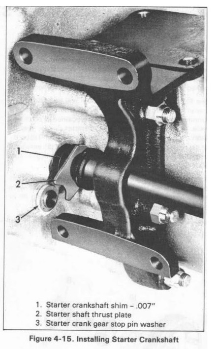
is not within specified limits of .001 to .007 in. it is absolutely
necessary to shim crank shaft. Use .007 in. thickness Shim, Part No.
6802, between crankcase and thrust washer to obtain correct fit as shown
in Figure 4-15.
Examine starter crank gear assembly (12) for wear and damage. Pay
particular attention to cam plate (20) ears for wear or bent condition.
Check for loose cam plate rivets (19) that may result in cam plate
separating from crank gear. Cam plate may be replaced providing gear
(12) is in good condition. When riveting new cam plate to crank gear,
insert rivets from gear side.
Check lockwasher (10) and oil seal (13), if worn or damaged, replace
parts.
Bronze bushings (16) are a press fit in transmission sprocket cover (5)
and left crankcase. Bushings are long life parts and will seldom require
replacement, however, if shaft (11) is not badly worn and excessive
starter crank shaft radial play is noted, bushings should be replaced.
When installing sprocket cover bushing be sure to correctly align hole
in bushing with cover grease fitting channel.
Starter gear stop pin (21) and washer (22) ordinarily will not require
replacement, and it is recommended procedure to inspect and replace stop
pin only with engine removed from chassis. Stop pin is a press fit in
crankcase. Washer is locked in place by peening stop pin end.
ASSEMBLING (Figure 4-14)
Install oil seal (13) in left crankcase. Insert crankshaft through hole
in motor mount. Slip thrust plate (15) on starter crankshaft (11), flat
side of plate up as positioned on motorcycle. Insert steel shims (14) on
crankshaft if needed, as described under "INSPECTION AND REPAIR." and
in-stall crankshaft in left case engaging notched thrust plate (15) with
stop pin washer (22) using grease to hold in place (see Figure 4-15).
Turn starter crankshaft until notch (A, Figure 4-14) is tothe rear as
positioned on motorcycle. Place starter crank gear on squared end of
shaft, recessed portion of cam plate facing down, end of slot against
stop pin as shown in Figure 4-16. When positioning crank gear (12) on
shaft (11) be extremely careful that thrust plate does not become
dislocated from stop pin washer (see Figure 4-15).
Slip lockwasher (10) over crankshaft end (11) engaging prong of washer
with hole in crank gear face. Install and securely tighten crank nut (9)
to 40-45 ft-lbs torque, with flat side of nut against washer.
Slip starter ratchet gear (6) over spacer (7), grooved side of gear
bushing against lip of spacer collar. Position small end of spring (8)
in clutch gear bushing groove.
Place starter ratchet gear assembly on ratchet gear, compressing spring
(8) and at the same time turning starter crank gear to permit meshing of
gear teeth.
Return starter crank gear to original position as shown in Figure 4-16,
with ratchet gear held against cam plate by spring tension.