Harley Davidson Touring Models 84-98 FLH, FLHT, FXR. Service manual - page 2
Telescoping and Small-Bore Gauges
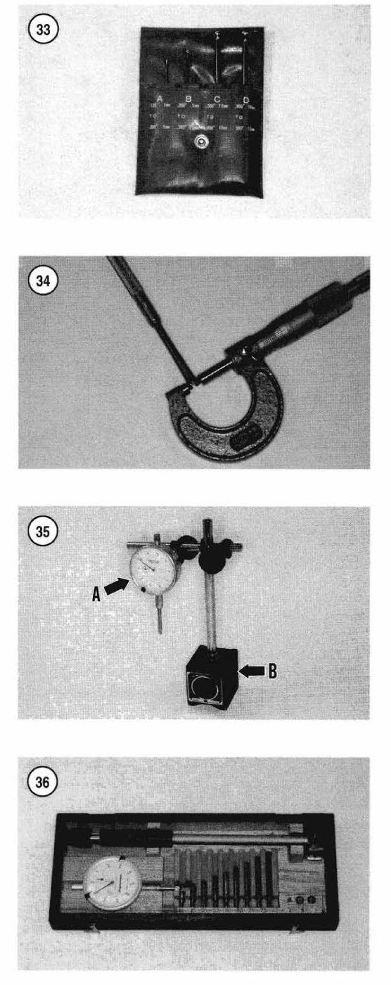
Use telescoping gauges (Figure 32) and small-bore gauges (Figure 33) to
measure bores. Neither gauge has a scale for direct readings. Use an
outside micrometer to determine the reading.
To use a telescoping gauge, select the correct size gauge for the bore.
Compress the movable post and carefully insert the gauge into the bore.
Carefully move the gauge in the bore to make sure it is centered.
Tighten the knurled end of the gauge to hold the movable post in
position. Remove the gauge and measure the length of the posts.
Telescoping gauges are typically used to measure cylinder bores.
To use a small-bore gauge, select the correctly sized gauge for the
bore. Carefully insert the gauge into the bore. Tighten the knurled end
of the gauge to carefully expand the gauge fingers to the limit within
the bore. Do not overtighten the gauge because there is no built-in
release. Excessive tightening can damage the bore surface and damage the
tool. Remove the gauge and measure the outside dimension (Figure 34).
Small bore gauges are typically used to measure valve guides.
Dial Indicator
A dial indicator (A, Figure 35) is a gauge with a dial face and needle
used to measure variations in dimensions and movements. Measuring brake
rotor runout is a typical use for a dial indicator.
Dial indicators are available in various ranges and graduations and with
three basic types of mounting bases: magnetic (B, Figure 35), clamp or
screw-in stud. When purchasing a dial indicator, select one with a
continuous dial (A, Figure 35).
Cylinder-Bore Gauge
A cylinder-bore gauge is similar to a dial indicator. The gauge set
shown in Figure 36 consists of a dial indicator, handle, and different
length adapters (anvils) to fit the gauge to various bore sizes. The
bore gauge is used to measure bore size, taper and out-of-round. When
using a bore gauge, follow the manufacturer’s instructions.
Compression Gauge
A compression gauge (Figure 37) measures combustion chamber (cylinder)
pressure, usually in psi or kg/cm2.