Great Wall V200. Service Manual - part 4


  Index      Great Wall     Great Wall V200. Service Manual


Search            copyright infringement  


Content      ..     2      3      4      5     ..


Great Wall V200. Service Manual - part 4


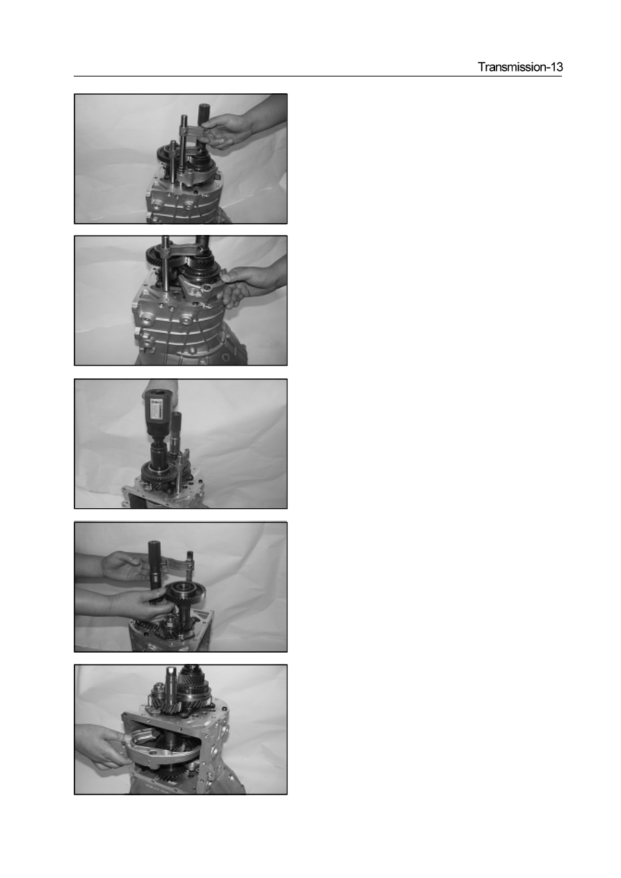
e. Remove the gear 3/4 declutch shift shaft assembly

f. Remove the reverse gear 5 shift fork

18. Remove the lock nut of intermediate shaft

Caution:  When install the lock nut of intermediate shaft , the

tightening torque is 160-190N·m

19.Remove the Gear 1/2 declutch shift shaft assembly, intermediate

shaft  rear ball bearing, 5th-Gear drive gear

20. Remove the Gear 1/2 shift fork

-------------------------------------------------------------------------------------------------------------------------------------------------------------

21.Use the special tools to remove the second shaft lock nut

Caution: When install the second shaft lock nut, the  tightening

torque is :   250-270N·m

22.Remove the thrust plate

23.Use the magnetic rod to remove the steel ball.

24.Remove the 5th-Gear driven gear assembly

Caution: When install the 5th-Gear driven gear assembly, it should

use the plug gage to test the 5th-Gear driven gear assembly axial

clearance, ensure the axial clearance is  within 0.170-0.284mm

25.Remove the 5th-Gear driven gear needle bearing

-------------------------------------------------------------------------------------------------------------------------------------------------------------

27. Use the pliers to remove the split pin on the reverse shaft lock

      nut.

28. Use the special tools to remove the reverse lock nut

Caution: when install the reverse lock nut, the tightening torque

is within 20-60N·m

29. Remove the thrust plate

30. Remove the 5th/reverse -Gear synchronizer assembly

a. Use the special tools to remove the 5th/reverse -Gear synchronizer

assembly

26. Remove the synchronizer gear ring

Caution: When install the synchronizer gear, it should use the

plug gage to test the synchronizer gear ring axial clearance, en-

sure the axial clearance is within 1.25-1.65mm

-------------------------------------------------------------------------------------------------------------------------------------------------------------

31. Remove the reverse gear

32. Remove 2 needle bearings of reverse gear

33. Remove the reverse driven gear

34. Remove the needle bearing of reverse driven gear

b. Remove the sleeve and 5th/reverse -Gear synchronizer assembly

-------------------------------------------------------------------------------------------------------------------------------------------------------------

35. Remove the reverse drive gear

36. Remove the intermediate shaft spacing ring

37. Remove 8 countersunk screws

Caution: when install the countersunk screw, the tightening torque

is within 15-22N·m

38. Remove the support axial lock plate

39. Remove the air duct grease baffle

-------------------------------------------------------------------------------------------------------------------------------------------------------------

Disassembly of clutch housing assembly /bearing
housing assembly

40. Use the special tools to remove the reverse shaft

Use the magnetic rod to take out 2 interlocking pins

Remove the first bearing block assembly

a. Use the special tools to install 6 M8 bolts.

Caution: When install 6 M8 bolts, the tightening torque is 10-

13N·m

Clutch housing assembly  / Bearing housing assembly

bush

   oil seal

Used component which can not be used any more.

throwout bearing
assembly

 washer 8

¦ non-standard spring

first bearing

first shaft assembly

 needle bearing

second shaft assembly

  ¦circles for shaft

¦adjusting shim

leather cup

separation rocker arm assembly

 separation rocker arm ball support

clutch cylinder assembly

front space ring of intermediate shaft

 intermediate shaft assembly

 aluminum waher

 Specified torque

-------------------------------------------------------------------------------------------------------------------------------------------------------------

b. Remove the first bearing blocks assembly ; take out the adjusting

shim

Caution: It should select the adjusting shim when install the

adjusting shim

43. Remove the bearing snap ring

44  Remove the intermediate shaft assembly

45. Remove the first shaft assembly

46. Remove the needle bearing


Mark

-------------------------------------------------------------------------------------------------------------------------------------------------------------

47. Remove the 3rd/4th-Gear shift fork

Remove the second shaft assembly

a. Use the rubber hammer to knock the second shaft

b. Remove the needle bearing bushing of reverse driven gear

c. Remove the double inner-race ball bearing assembly

d. Remove the second shaft assembly

-------------------------------------------------------------------------------------------------------------------------------------------------------------

Secondary shaft assembly

49. Disassembly of second shaft assembly

a. Remove the second shaft rear retainer

Caution:   It should select the circlip for shaft when install the

circlip for shaft.

b. Remove the 3rd/4th-Gear synchronizer assembly

c. Remove the 3rd/4th-Gear synchronizer gear ring

Caution: When install the 3rd/4th-Gear synchronizer gear ring, it

should use the plug gage to measure the end surface clearance of

gear ring to ensure it is within 1.25-1.65mm

¦circlips for shaft

3rd/4th-Gear syn-

chronizer assembly

1st/2nd-Gear synchronizer assembly

 synchronizer gear ring

3rd-Gear driven gear assembly

needle bearing

second shaft

2nd-Gear driven gear assembly

2nd-Gear synchronizer gear ring

 needle bearing

sleeve

1st-Gear synchronizer gear ring

1st-Gear driven gear assembly

double inner-race

m:    specified torque

Used component which can not be used any more.

-------------------------------------------------------------------------------------------------------------------------------------------------------------

d. Remove the 3rd-Gear driven gear assembly

Caution: When install the 3rd-Gear driven gear assembly, it should

use the plug gage to measure the 3rd-Gear driven gear assembly

axial clearance to ensure it is within 0.17-0.284mm

e. Remove the 3rd-Gear driven gear needle bearing

f. Use the special tools to press the second shaft to remove the inner

race of double inner-race ball bearing.

Remove the 1st-Gear driven gear

     Caution: When install the 1st-Gear driven gear, it should use the

  plug gage to measure the 1st-Gear driven gear axial clearance to

 ensure it is within 0.17-0.284mm.

h. Remove the 1st-Gear driven gear needle bearing

-------------------------------------------------------------------------------------------------------------------------------------------------------------

Transmission-23

i. Remove the sleeve

j. Remove the 1st-Gear synchronizer gear ring

k. Remove the 1st/2nd-Gear synchronizer assembly

l. Remove the 2nd-Gear synchronizer gear ring , 2nd-Gear driven gear

and second shaft

Caution: When install the 2nd-Gear driven gear, it should use the

plug gage to measure the 2nd-Gear driven gear axial clearance to

ensure it is within 0.17-0.284mm

-------------------------------------------------------------------------------------------------------------------------------------------------------------

2. Operation of 4WD

The operating auxiliary steering column can be shifted to 4WD status.

For position of auxiliary steering column and corresponding operating

condition refer to table.

3. Caution for operation:

a. Do not use 4WD in good surface, otherwise the tyre and components

of drive system will be damaged easily and increase the consumption

of fuel, and cause the noise of drive system.

     b.   Please run in 1st-Gear under “4L” gear position when run  in very

  low speed in field.

Operating instruction of transmission SC5M4D-C

1.The schematic diagram of transmission operating gear position

    is on the handle of steering column.

During the process after vehicle is started and in traveling, it must

step the clutch pedal to bottom before the shifting. If need shift from

5

th

-Gear to reverse-Gear, it should move the shifting bar to the neutral

position of 3rd/4th-Gear. Shift to R-Gear after stop the vehicle stably,

otherwise, it can not shift.

During the traveling process. It should always pay attention to the

shifting to make the vehicle matches to the speed of engine. The

correct shifting can improve the economical efficiency and prolong

the service life of engine. Do not shift from high-Gear to low-Gear on

the condition that the pointer of tachometer may enter into red area,

otherwise, the engine will be damaged.

Warning: Do not shift to reverse-Gear when the vehicle moves

forwardly, otherwise the transmission will be damaged.

hand hall of main steering column

hand ball of auxiliary steering column

Auxiliary steering 

column position 

drive Operating 

condition 

2H 

2WD 

Use this gear position when run in the general railway and high speed highway.   

4H 

High speed 4WD 

Use this gear position when run in the deep snowland, sand ground or uneven road 

in normal speed. 

Neutral gear 

When use the gear position during using of winch, it could not drive the vehicle. 

4L Low 

speed 

4WD 

Use this gear-position when run in uneven road such as mud land or climbing or 

downward  (especially when need increase the power). 

-------------------------------------------------------------------------------------------------------------------------------------------------------------

Transmission-25

2.Replacement of oil-seal of transfer case

The replacement of transfer case oil seal is shown as figure. Disconnect

the drive shaft from the transfer case, use the flat head screwer to

remove the oil seal

Caution: Do not damage the housing hole during the disassembly.

Then use the special tools to  knock the transfer case oil seal into

the transfer case. It should pay attention to the installation dire

tion of oil seal. The oil seal is flush with the port of transfer case.

Shown as figure. Coat the lip of oil seal with the specified general

synthetic gear oil.

3. Disassembly and check of transmission

The preoperation before the removal and after installation of

transmission is : When remove and install the manipulator cover

assembly, drain and fill with the specified transmission and transfer

case lubrication oil. When remove and install the front and rear drive

shaft, separate each  plug-in part of transmission from the vehicle.

Inspection of manipulator cover assembly:

The bolt dimension is different for different installation position. Do not

confuse it during the installation. It should install the fixing bolt A firstly.

The tightening torque of bolt A and B bolt is 15

22N

m.

installation position of fastening blot

bolt 

bolt 

bolt 

Repair of transmission SC5M4D-C

1. Inspection of oil level of transmission and transfer case:

Screw off the oil drainage screw plug of main box and transfer case;

drain all lubrication oil, tighten the oil drain plug to specified torque.

The torque is:  30

35N m. Fill the main box and transfer case with

the transmission oil through the oil filling port. The number is hyperbolic

gear oil SAE80W/90, comply with API GL-4. The oil quantities are

main box :   2.2 L, transfer case :   2.7 L. (for high and low temperature

environment refer to maintenance specification). Tighten the oil filling

screw plug to specified torque. The torque is:  30

35N

m.

front output shaft oil

seal   (SC

1802504)

rear output shaft oil seal

(SC

1802323)

transmission

transfer case

oil filling screw plug

oil-drain screw-plug assembly

(JK72

1701070)

oil filling screw plug

-------------------------------------------------------------------------------------------------------------------------------------------------------------

Transmission SC5M4D

C assembly

m:   specified torque

 Used component which can not be used any more.

transmission

separated case

 spring cylindrical pin

cylindrical

 compression spring

  steel ball 6.35

cylindrical compression spring

 reverse lamp

 switch bracket

wire clip

elastic cylindrical

pin 

manipulator cover assembly

washer 

test switch bracket

 select & shift seating

washer 

location spring

cylindrical pin

cylindrical compression spring

bush

wire clip

stud M10

1.25

-------------------------------------------------------------------------------------------------------------------------------------------------------------

Transmission-27

Manipulator cover assembly

Rear housing assembly

nut 

reverse lock
assembly

manipulator

cover assembly

ball head

rubber cover

auxiliary steering

column stop plate

bush

ball head base

washer

pin

 auxiliary steering

column assembly

handle of transfer case

 ball head

hood

ball head

rubber cover

stop plate of

main bar

    bush

ball head base

pin 

washer

master control lever assembly

handle of

gearlever

m:   specified torque

 Used component which can not be used any more.

odometer driven gear

assembly

odometer seating lock plate

14-19

14-19

oil seal 

dustproof seal

guide bushing

  rear housing

adjusting shim

24-33

26-36

aluminum gasket

mushroom lock spring

aluminum gasket

24-33

mushroom lock spring

26-36

30-42

m:   specified torque

     Used component which can not be used any more.

Pregummed component

Use the special tools

  steel ball 7.938 (3)

-------------------------------------------------------------------------------------------------------------------------------------------------------------

Disassembly of rear housing assembly

1.Remove the M8

18 hexagon bolt and the lock plate

Caution:  When install the M8

18 hexagon bolt, the tightening

torque is 14-19N

m

2.Remove the odometer driven gear assembly

Use the special tools to remove the odometer driven gear assembly

3.Remove the  rear cover assembly

Caution: When install 6 M10

1.25

30 hexagon bolts, the tightening

torque is 14-19N

m

b.Use the plastic hammer to knock the rear cover slightly and take out

the rear cover

c.Take out the adjusting shim

Caution: It should select the adjusting shim as follows when

install it.

mark

-------------------------------------------------------------------------------------------------------------------------------------------------------------


Content      ..     2      3      4      5     ..