Great Wall Hover. Manual - part 63
 

  Index      Great Wall     Great Wall Hover - service repair manual


Search            copyright infringement  


Content   ..  61  62  63  64   ..


Great Wall Hover. Manual - part 63


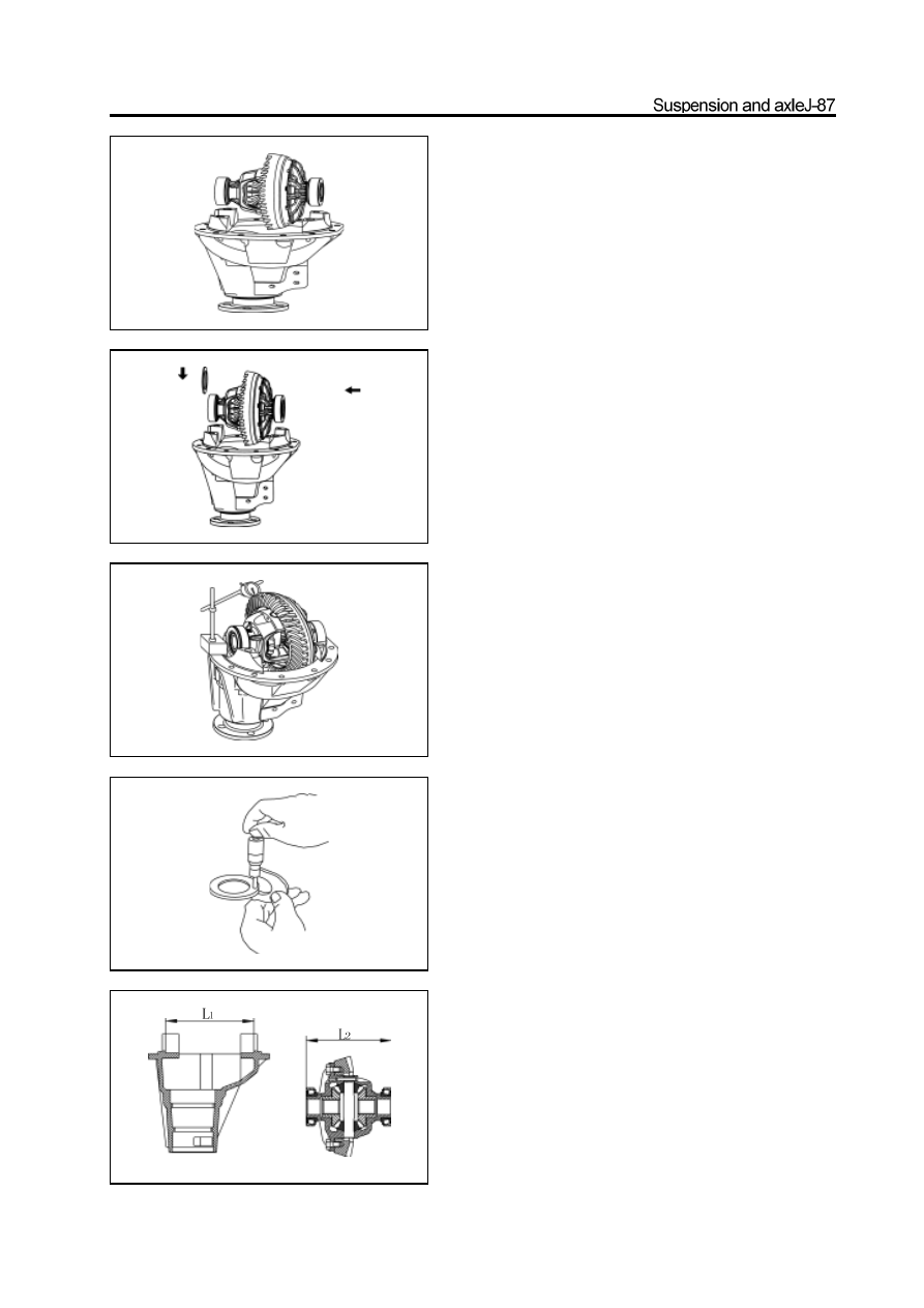
8. Place the differential assembly on the corresponding

position of front reducer housing.

9.Select an adjusting shim and insert it in a side of

side bearing outer race; push the differential assem-

bly to the side with adjusting shim.

10. Use the dial indicator to measure the gear side

clearance of driven bevel gear and drive bevel gear;

select out the adjusting shim in the side which meets

the rational clearance of 0.15mm.

11.Measure the thickness of the adjusting shim.

12. After select out one side adjusting shim, then

select theadjusting of another side according to that

the theoreticthickness of the adjusting shimofanother

side equals to subtracting the thickness of selected

shim and oppositiondistance L2 between outer race of

two side bearings of differential assembly from the

opposition distance L1 between two side bearings of

front reducer housing.

13. Place an adjusting shim in the position of front

reducer housing side bearing and close to exterior.

14. Install the other adjusting shim and the bearing

outer race of another side with the differential

assembly into the front reducer housing.

Remarks: Ensure the selected adjusting shim has

not gap with front reducer housing.

15. Rotate the driven bevel gear to make the differ-

ential assembly closed to the front reducer housing.

16. Use the dial indicator to measure the tooth side

gap between the drive and driven bevel gear.

The rational range of gap is: 0.15-0.25mm.

If the measured gap is beyond the range, then adjust it by

adding or reducing the thickness of shim. ( When add in

one side, the other side should be reduced with same

thickness)

Caution: Ensure the selected adjusting shim is

without clearance form front reducer housing.

17. Adjust the pre-applled axial load of side bearing.

a. Remove two adjusting shim, remeasure the thickness of two

adjusting shims.

b. Install the new adjusting shim with thickness 0.06-0.09mm

more than that of removed adjusting shim, then install it with

the differential in the reducer housing.

c. Remeasure the tooth side clearance between the drive bevel

gear and driven bevel gear.

Rational range of clearance: 0.15-0.25mm

Remarks: If the measured gap is beyond the range, then adjust

it by adding or reducing the thickness of shim. ( When add in

one side, the other side should be reduced with same

thickness)

Caution: Ensure the selected adjusting shim has not the

clearance with the front reducer housing.

18. Install the bearing gland of both sides and use

the wrench to tighten it to the specified torque.

specified torque : 90-115N

m

Remarks: Distinguish the left and right during assembly.

19. Use the torque measuring meter to measure the

total pre-applied load of front reducer.

specified torque : 1.8-2.4N

m

sound contact

large end contact

toe contact

select the adjusting washer which can make the drive gear close to the

driven bevel gear

select the adjusting washer which can make the drive

gear away form the driven bevel gear r

small end contact

dedendum contact

20. Check the meshing mark of drive and driven

bevel gear.

a. Paint 3-4 teeth with the red lead in three different positions

of driven bevel gear.

b. Hold the flange of drive gear; rotate the driven bevel gear in

clockwise and anticlockwise.

c. Check the contacting condition of gear tooth.If the meshing

mark of drive and driven bevel gear does not consist with

thatshown in figure, it should select the proper adjusting

washer for modification according to the detailed form of

meshing mark.

convex of driven

concave of driven bevel

d. Remove the drive bevel gear and use the special toolsto remove

           the large bearing of drive bevel gear beforereplacethe adjusting

     washer.

e.   Insert the new adjusting washer and usethespecial tools to

      press in the large bearing of drivebevel gear.

 f.    Place the adjusting washer above the large bearing on the

           drive  bevel gear, install the spacer in the reducer housing;

       install the drive gear flange andtighten the nut to the specified

           torque.

 g.   Remeasure the pre-applied load of drive gear bearing clearance

          and the total pre-applied load of reducer; ensure it meets the

          requirement.

21. Use the dial indicator to measure the axial and

radial run-out tolerance of . Drive bevel gear flange.

Max. Axial runout : 0.1mm

Max. Radial run-out tolerance: 0.1mm

Remarks: It should check the big and small bearing of drive

bevel gear  when the runout is more than 0.1mm.

22. Rivet the nut of drive bevel gear.


Content   ..  61  62  63  64   ..