Great Wall Hover. Manual - part 23
Automatic transmission-23
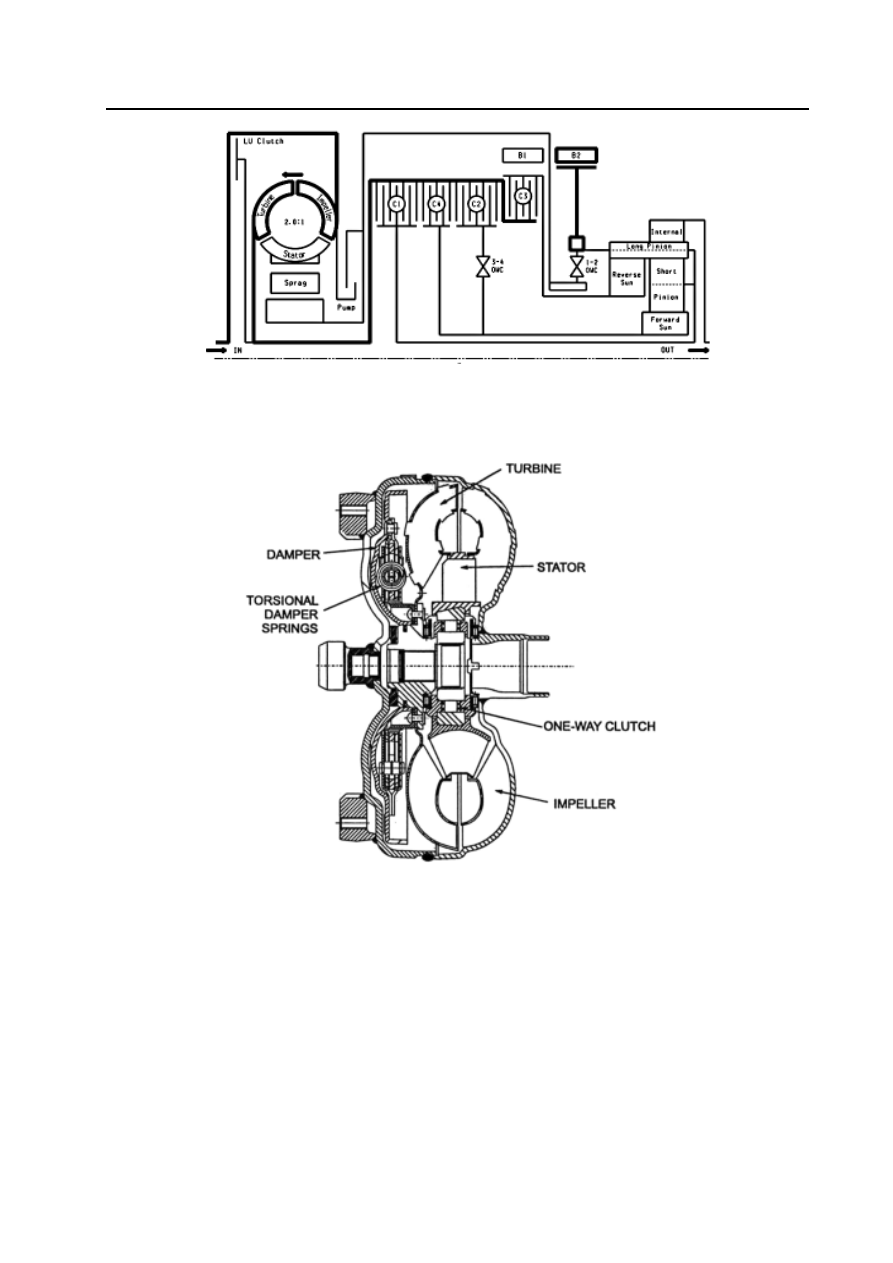
Figure 4.1 Power flow chart
Torque converter
The torque converter (refer to Figure 4.2) consists of the turbine, stator, impeller and a lock throttle brake and piston assembly.
Same as that of the traditional torque converter, the impeller is connected to the end cover of the torque converter. The turbine is
connected to the input shaft through the spline. The stator is installed on the pump housing through the one-way clutch .
Figure 4.2 Section of torque converter
The buffer and piston assembly can make the torque converter is locked in proper condition. The locking action only occurs
in the condition of specified throttle position opening and vehicle speed. When the hydraulic force makes the buffer and piston
assembly is coupled on the cover of torque converter, it can acquire the locking status. In this status, it can eliminate the
unnecessary sliding. It can increase the economical efficiency of fuel oil when the locking action is generated. When in locking
status, the torque buffer spring in the buffer and piston can absorb the torque fluctuation of engine
.
Clutch assembly
It has four types of clutch assembly (refer to Figure 4.3). All clutch assemblies are composed of several layers of steel plate and
friction disk.
Clutch C1 When it is engaged, the drive shaft drive the planet carrier. The condition occurs in 3
rd
and 4
th
Gear.
Clutch C2 When it is engaged, the drive shaft drive the forward central gear through the 3-4 one-way clutch. The conditio
occurs in 1
st
, 2nd and 3
rd-
Gear condition.
Clutch C3 When it is engaged, the drive shaft drive the backward central gear. The condition occurs in R-Gear position.
Clutch C4 It can provide the brake of engine during overspeed when is engaged, The condition occurs in manual 1
st
, 2
nd
and 3
rd
–Gear, also in automatic 2
nd
and 3
rd
-Gear to avoid the unfavorable inertia rotation of freewheel.