Great Wall Florid. Manual - part 23
 

  Index      Great Wall     Great Wall Florid - service repair manual 2008 year


Search            copyright infringement  


Content   ..  21  22  23  24   ..


Great Wall Florid. Manual - part 23


GWFLORID Maintenance Manual

90

Vehicle road test methods

1. Drive the vehicle and find out if the swaying is coming from the front tires or the back tires. Then replace the 

identified problem tire with a good tire (one that has been tested on the same model of vehicle). 

2. If unable to determine the problem tire, replace the rear wheels. Continue with the road test. If the driving 

condition obviously changes, replace the original tires, and only switch one at a time until the problem tire is 

identified. 

3. If no obvious improvement, replace all four tires with good tires, and then replace the original tires one by 

one following the steps mentioned above. 

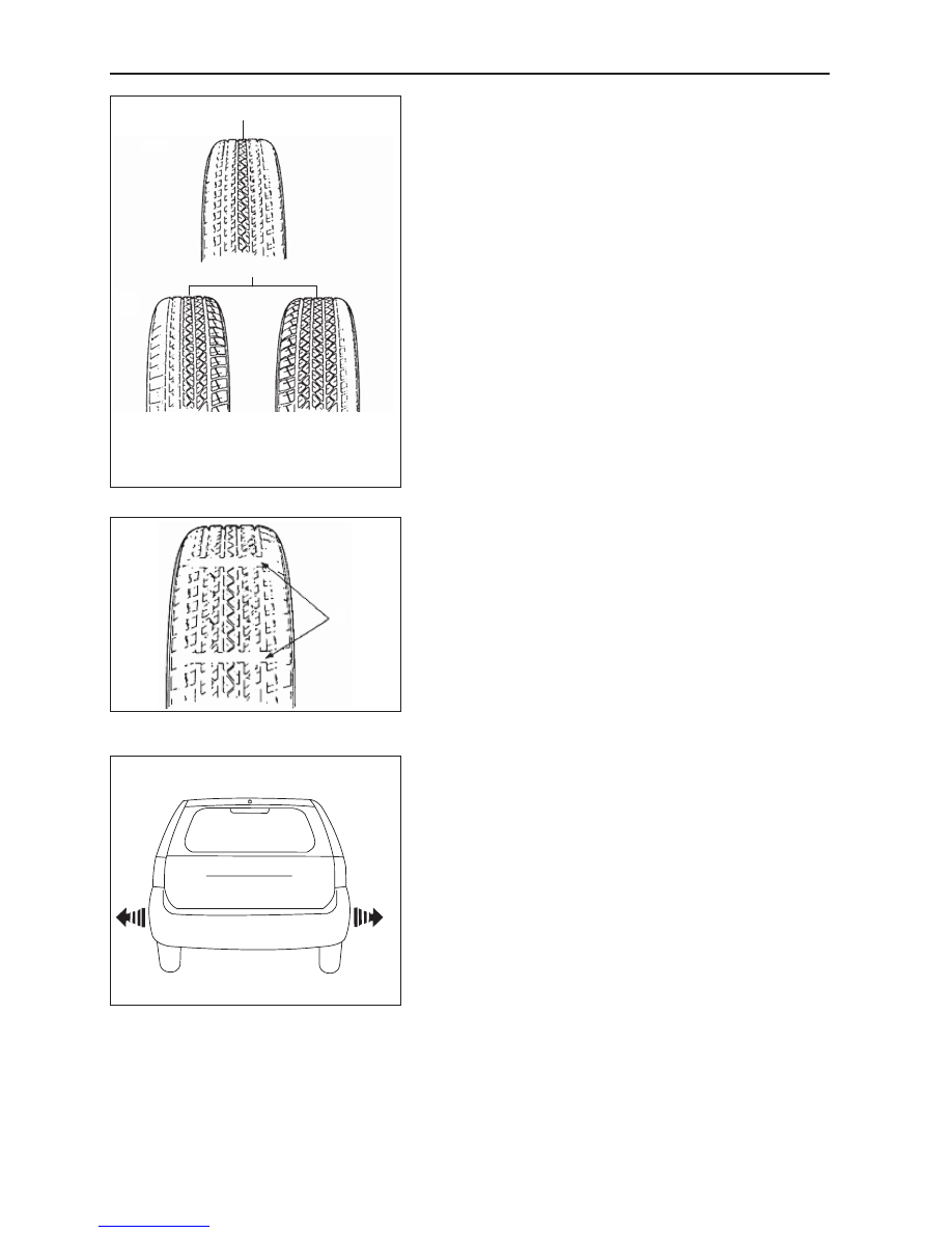
Tire's abnormal wear and tear

Tire's abnormal wear and tear includes uneven and excessive 

wear  of  the  tire. There  are  many  causes  for  this.  For 

example, improper tire pressure, tire rotation has not been 

timely maintained, bad driving habits, abnormal front wheel 

location, etc. 

Change the tires when the below situations happen: 

1. When the extents of wear and tear of the front and rear 

tires are different. 

2. When any of the tire's tread has uneven wear and tear. 

3. When the extents of the wear and tear of the left and right 

front tires are different. 

4. When the extents of wear and tear of the left and right rear 

wheels are different. 

5. When the groove of the tire tread wear appears abnormal 

and the tire's contact area starts to flatten. 

Inspect  the  front  wheel  alignment  when  the  following 

situations occur: 

1. When the extents of the wear and tear of the left and right 

front tires are different. 

2. When any of the tire's tread has uneven wear and tear. 

3. When the tread pattern strip or pattern block of a front 

tire's single side is badly worn. 

[A]

[B]

[A]: Steering problems, air pressure not sufficient, or 

tire  rotation has not been timely maintained. 

[B]: Abnormal front wheel alignment, tire or wheel 

structure is not the same. 

Radial tire sway

Here the sway means the vehicle's front or rear part shakes 

from side to side, together or individually. Tire sway is 

caused by the steel wire belt inside the tire not being straight. 

The sway is the most obvious when the vehicle runs at the 

speed of 8-48 km/h. 

Road tests can help finding malfunctioning tires. If the 

malfunction is with the rear tires, then left and right shaking 

or "swaying" would take place at the back of the vehicle. 

Here the driver of the vehicle would feel as if someone were 

pushing from one side of the vehicle. 

If the malfunction is with the front tires, swaying would be 

even more obvious. The metal plate in the front may seem 

moving back and forth, and the driver feels as if he/she were 

at the vehicle's center of rotation.

Wear marks

There are several tread wear marks (refer to location A in the 

diagram shown on the left) inside of the tire's pattern groove. 

These marks indicate that the tire has been worn to the point 

of replacing. 

Before the tire's usage limit, indicated by the remaining 

pattern's depth, reaches 1.6 mm (and its main pattern groove 

bottom protrudes to the same level), for your safety, please 

replace the tire. 

When serious eccentric wear leads to the partial protrusion 

of the cord fabric level, or outside objects damage the tire to 

a depth that reaches the cord fabric level or steel band level, 

stop using the tire. 

A

91

Suspension System

Deviation judging methods

"Deviation" means that, when no one is in control of the steering, the vehicle does not move in a straight line 

while driving on a straight and leveled surface. 

Deviation causes:

• Incorrect tire and front wheel alignment,

• Braking force is not even, 

• Tire structure problems.

Tire production and manufacturing methods can also lead to vehicle deviation. For example, the arrangement of 

the tires inner steel wire belt. A steel wire belt which is inside the radial tire deviating from the tires centerline 

can create lateral force when the tires are rolling in a straight line. If one of the tire's diameter is larger than the 

other, the tire will tend to roll to that side, this also creates lateral force (a tapering effect) leading to vehicle 

deviation. When the front wheel alignment is found to be correct and in proper order, the above process is also 

applicable in judging tire deviation. Rear tires cannot cause deviation. 

After solving, if working, 

switch the tires again

Return the tires to their 

initial positions and inspect 

the front wheel alignment

After solving, 

switch the tires again

Tire  rotation

For equal wear or tear for the tires, please rotate the tire 

positions timely. Swapping principle shown on the left. 

Radial tires should be regularly switched, and add pressure 

according to the regulations. 

Caution:  

Due to structural reasons, radial tires usually quickly 

receive most of its wear on the shoulders, especially 

the front tires. Do a tire rotation per 8000-12000 km, 

and the tire life can increase by 20%. This makes 

regular tire rotation especially useful. 

Test by driving back and forth 

on a straight and leveled road

Tends to lean 

in the same 

direction

If the problem is not yet 

solved, it means the "good 

tire" is in fact not good

If the problem is not 

yet solved, replace the 

other side's front tire 

with a "good tire"

Replace one of the 

front side tires with 

a "good tire"

Tends to 

lean in the 

other direction

Front

Rear

Adjust the tire pressure to 

the recommended level

After swapping the right and left front 

tires, perform the above test again

After solving, 

switch the tires again

GWFLORID Maintenance Manual

92

Wheel

General tire balancing procedures

Clean out the accumulated dirt and debris from the inside of the rim. 

Warning:  

The gravel on the tread must be eliminated to avoid flying out and injuring the operator when 

undergoing rotational balancing. This is also a good way to acquire better balance. First thoroughly 

inspect  the  tire's  damaged  condition,  then  according  to  the  balancing  device  manufacture's 

recommendations, carry out the balancing operation. 

Off-vehicle balancing

Most off-vehicle balancers are more accurate and convenient than on-vehicle rotational balancers. They are 

also able to perform dynamic (two sided) balancing. Although it does not correct drum brake and brake disc 

imbalance like on-vehicle balancing, it achieves the same effect based on its accuracy. 

On-vehicle balancing

On-vehicle balancing is different based on equipment and tool manufacturer. Therefore, when performing 

balancing operations, be sure to comply to each manufacturer's operating instructions. 

Warning: Control the wheel rotation speed to make sure the speedometer stays within 55 km/h. 

This restriction is necessary because when a driven wheel slides while the other one stays still, the 

speedometer will display only half of the actual wheel speed. When a wheel is sliding, be extremely 

careful, because sliding wheels can reach very high speeds. This may lead to the tire rubber peeling 

or differential damage, which may cause serious personal injury, or damage to the vehicle. 

Tire installation and removal

•  Install or remove tires with a tire changer. When operating machinery, make sure to comply to the machine 

manufacturers operation manual. Please do not change tires merely with manual hand tools or tire installation 
crowbars. This will damage the tire chafer or the vehicle wheel's rim. 

•  Use a wire brush or coarse steel wool to clean off grease and old rubber, as well as light rust or corrosion from 

the rim tire bead's tire chafer seat. Before tire installation or removal, first use the indicated tire lubricant to 
thoroughly lube the tire chafer portions one time. 

•  After installing the tire, inflate it to the specified pressure and make sure the tire bead is properly seated.

Warning: Do not over-inflate the tire. If the tire bead severally expands and exceeds the safety limit, 
it may burst and cause serious personal injury. While inflating, do not exceed the specified pressure.
If the specified pressure does not allow the tire bead to sit properly, deflate the tire, re-lubricate, and 
then re-inflate. 

Spare tire usage

•  Spare tire standard inflation pressure: 420 kPa. 
•  Spare tire pressure measurements should be taken under normal temperature conditions. 
•  After inflating the spare tire, soapy water should be used to check if the air nozzles core is leaking air, then 

lock on the air nozzle cap. 

•  The spare tire should always be kept in a useable state. Check the air pressure at least once a month. 
•  When the spare tire's working limit, indicated by the remaining pattern's depth, reaches 1.6 mm (and its pat-

tern groove bottom protrudes to the same level), for your safety, please stop using the spare tire.  

Caution:  

 • The " " symbol on the tire bead of the spare tire in-

dicates the set position of the wear index (shown on 

the left). 

 • The spare tire's maximum driven speed is 80 km/h, 

and maximum distance 200 km per trip. 

 • Each vehicle is allowed to use only one spare tire. 

 • The spare tire is only used as a temporary backup. 

Please go to a professional service station immediately 

to get the initial tire repaired or replaced. 

93

Suspension System

Dynamic balance and static balance

There are two types of wheel balance: static and dynamic. 

Picture 1 shows static balance. Picture 2 shows dynamic 

balance. 

Static balance means that the weight distribution around the 

wheel is equal. If the wheel is static and unbalanced, violent 

vibrations may be created, called jump vibration.This kind 

of situation can ultimately lead to the uneven wear and tear 

of the tires. Shown in diagram 1. 

Dynamic balance means that the weight distribution on the 

two sides of the medium plane of the wheel is equal, so 

during the rotation process, the tire assembly cannot create a 

tendency for the medium plane of the wheel to shift from one 

side to the other. If the wheel is dynamic and unbalanced, it 

can create a shimmying effect. Shown in diagram 2. 

1. Wheel shimmy important points

[C]: Counterweight not yet added

2. Locations to add counterweight

[D]: Counterweight added

3. Axis

Wheel maintenance

Do not use welding, heating, or hammering to repair wheels. All damaged wheels must be replaced. 

If the vehicle's wheel is twisted or deformed, sunken or depressed, having too much horizontal or radial hop, 

leaking air from the welded parts, stretched out at the bolt holes , having flimsy nut bolt lock, or severely rusty, 

the wheel must be replaced. When the wheel is hopping too much, it will lead to undesirable vibrations. 

When replacing the tire, be sure that the load capacity, diameter, rim width, offset distance, and the installation 

structure of it, are equal to the settings of original wheel. If the wheel dimensions are not appropriate, this will 

influence the wheel and bearing's life, brake cooling effect, speedometer and odometer calibration, vehicle 

ground clearance, as well as the clearance between the tire and the vehicle body, and the tire and vehicle chassis. 

Wheel (steel wheel) removal

1. Remove the wheelhouse and loosen the nuts, 1-2 turns is 

enough.

2. Hoist the vehicle.

3. Screw off the nuts and remove the wheel.

Nut tightening torque: 110±10 N·m

Caution: Heating methods absolutely must not be used 

to loosen tightened wheels, otherwise the heat will 

reduce its use life and damage the hub bearing.

Wheel (steel wheel) installation

Installation according to the reversed instructions used for 

removal, and pay attention to the following requirements:

Wheel nuts must be tightened in proper order and according to 

the specified torque, as to avoid wheel or brake disc deformity. 

When installing the wheel house, be sure to line up the wheel 

housing notch locations with the inflation nozzle. 

Tightening sequence: A – C – B – D

Caution: Before installing the wheel, first clean off the 

corrosion on the wheel's mounting surface and drum 

brake or brake disc's installation surface with a wire 

brush, in order to make the wheel installing easier by 

making the space between its metal firmly connect 

to the mounting surface, otherwise it may lead to the 

wheel nuts loosening to the extent that the vehicle's 

wheel may come off while driving some day. 

1

3

2

[A]

[B]

1. Wheel hop important points

[A]:  Counterweight not yet added

2. Locations to add counterweight

[B]:  Counterweight added

3. Axis

Diagram 1

Diagram 2

[C]

[D]

1

3

2

A

B

C

D


Content   ..  21  22  23  24   ..