Geely Diagnosis Flow. Manual part - 26


  Главная      Geely     Common Malfunction Diagnosis Flow of Geely Automobile - 2008 year


поиск по сайту           


содержание   ..  20  21  22  23  24  25  26  27   ..


Geely Diagnosis Flow. Manual part - 26


101 

Low-voltage side: 1# connected with ECU20# earthing channel of No. 1 coil primary winding;   
2# connected with ECU1# earthing channel of No. 2 coil primary winding; 
3# and 4# connected both to power source (+);   
High-voltage side: 1, 2, 3, 4 respectively connected with spark plug of engine cylinder of same 
numbering;  
Simple measuring method: 
1. (Remove the connector) place digital multimeter to ohm position, and two pens are 
respectively connected to two pins of primary winding, resistance is 0.41-0.53Ω for Type ROV, 
and 0.42-0.58Ω for Type 2X2 under 20℃; and for secondary winding, resistance is 7-9kΩ for 
Type ROV, and 11.2-14.8kΩ for Type 2X2;   
2. Take out spark plug within the engine, and connect with high voltage line, and make its casing 
earthed; start the starting motor and observe flashover of spark plug;   


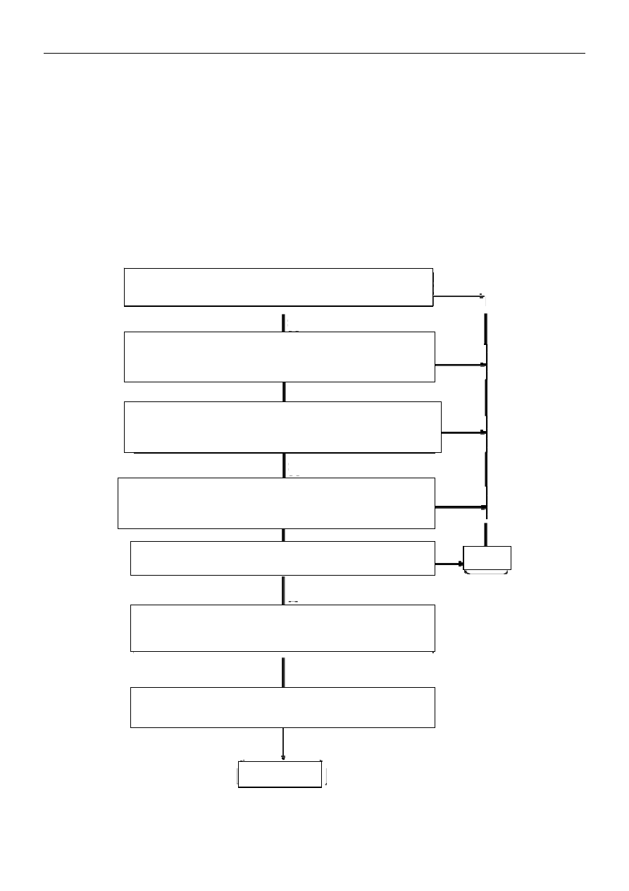
Diagnosis flowchart for ignition coil 


1. Check and confirm connection between ignition coil and ECU is loosening, 

and terminal damaged?   

2. Check ignition switch to terminal 1 is open circuited or shorted to ground? 

Check support of ignition coil is earthed?   

3. Ignition switch closed; remove joint of ECU and ignition coil; and check ECU 

and ignition coil is shorted circuited to voltage source?   

4. Check ignition coil terminal 2 to ECU terminal 1 is shorted to earth?   

5. Check ignition coil terminal 2 to ECU terminal 1 is open circuited?     

6. Replace ignition coil; confirm malfunction still exists after replacement?   

7. Replace ECU   

Completed  

Repair  

Y

Y

N


102 


No.058 Quick diagnosis for throttle valve position sensor   


Function: this sensor is for providing information about outer corner of throttle valve to ECU, 
based on which, ECU could obtain information related to engine load, condition (such as startup, 
idling speed, dragging, partial load, full load) and acceleration and deceleration.   


Principle: this sensor is actually corner potentiometer with linear output characteristics. Rocker 
arm of potentiometer is installed with throttle valve at the same axis; when throttle valve rotates, 
it will make rocker arm slide to certain position; potentiometer will output voltage signal 
proportional to throttle valve position.   


Definition of sensor pin:   
1#30#  earthing; 
2#12#    connected to 5V reference voltage;   
3#53#  sensor signal output 
Simple measuring method: 
1. (Remove the connector) place digital multimeter to ohm position, and two pens are 
respectively connected to 1#, 2# pins of sensor, with its resistance as 2kΩ±20% under normal 
temperature;  
2. Two pens are respectively connected to 1#, 3# pins; rotate throttle valve, and its resistance 
will increase as opening of throttle valve, and for 2#, 3# pins, the opposite condition will occur; 
Note: while observing changes of resistance value, observe it jumps largely; if so, it indicates that 
the signal has break point; then replace it;     
3. (Connect the connector) Open ignition switch and do not start the engine, then place digital 
multimeter to direct current voltage position, with black pen for earthing, and red pen for 2# pin; 
which shall have 5V reference voltage at this point; connect 3# pin and measure signal output; 
when throttle valve is fully closed, its voltage value is about 0.3V (specific value related to vehicle 
model); when throttle valve is fully opened, its voltage value is about 3V (specific value related to 
vehicle model). 


103 

Diagnosis flowchart for throttle valve position sensor 


1. Switch on ignition switch, the engine not started 

Change opening of throttle valve, and check it is indicated as C degree to 

about 34 degree with diagnosis instrument?   

2. Close ignition switch; take out sensor joint; ignition switch switched on. 

Opening of throttle valve is indicated as 10 degree?   

3. Check signal circuit of the sensor (53-3) is shorted circuited or shorted to 

earth with B+? 

4. Check reference voltage circuit of the sensor (12-1) is open circuited, 

shorted to earth or shorted to B+? 

5. Check signal circuit of the sensor (53-3) is open circuited, shorted to earth 

or shorted to B+? 

6. Check earth circuit of the sensor (30-2) is open circuited, shorted to earth 

or shorted to B+? 

7. Ignition switch closed; signal terminal 3 of sensor is shorted circuit to 

reference voltage terminal 12 of ECU; ignition switch turned on, opening of 

throttle valve is fully opened 84 degree (about 5V)? 

8. Ignition switch turned on; measure voltage between earth circuit (terminal 

2) and reference voltage (terminal 1) is 5V with the voltmeter?   

9. Replace throttle position sensor   

10. Replace ECU 

Completed 

Repairs

Y


104 


No.059 Quick diagnosis for inlet pressure temperature sensor   


Function: this sensor is for measuring absolute pressure and inlet temperature of intake manifold, 
and providing information related to engine load and inlet temperature. Principle: piezoelectric 
transducer is for measuring inlet pressure, and will provide "load signal" to the controller 
according to difference between atmospheric pressure and intake manifold pressure; provide 5V 
via controller and feed 0-5V to the controller according to difference of inlet pressure. Type NTC 
(negative temperature coefficient) sensor is for measuring inlet temperature, and resistance 
changes by inlet temperature, and this sensor will transfer one voltage indicating changes of inlet 
temperature to the controller.   


Definition of sensor pin:   
#30#  earthing;  
2#44#  temperature signal output;  
3#12#    connecting 5V reference voltage;   
4#7#  pressure signal output; Simple measuring method: 
1. Read malfunction code via engine diagnosis instrument and check malfunction information by 
referencing parameter of inlet temperature and inlet pressure. When the vehicle is not started, 
inlet pressure is close to the local atmosphere pressure, generally as one atmosphere pressure; 
after startup, pressure is reduced to 300~400kpa, and inlet temperature is ambient temperature 
at that time;   
2. For temperature sensor, (remove the connector) place digital multimeter to ohm position, and 
two pens are respectively connected to 1#, 2# pins of sensor, and rated resistance is 2.5kΩ±5% 
under 20 , and other corresponding resistance values could be measured from characteristic 

curve above. When measuring, use simulation method, specifically, supply air to the sensor via 
air blower (do not approach too closely), and observe changes of sensor resistance, which shall 
be reduced at this point;   
3. For pressure sensor, (connect the connector) place digital multimeter to DC voltage position, 
with black pen for earthing and red pen respectively connecting with 3#, 4# pins. At idling speed, 
3# pin shall have 5V reference voltage, and voltage of 4# pin is about 1.3V (specific value related 
to vehicle model); under empty load, slowly open throttle valve, and voltage of 4# pin is not 
greatly changed; quickly open throttle valve, and voltage of 4# pin could reach about 4V 

air intake manifold absolute pressure and air 

intake temperature sensor 


содержание   ..  20  21  22  23  24  25  26  27   ..