Geely Emgrand X7. Manual part - 610


  Главная      Geely     Geely Emgrand X7 - Manual


поиск по сайту            


содержание   ..  609  610  611  ..


Geely Emgrand X7. Manual part - 610
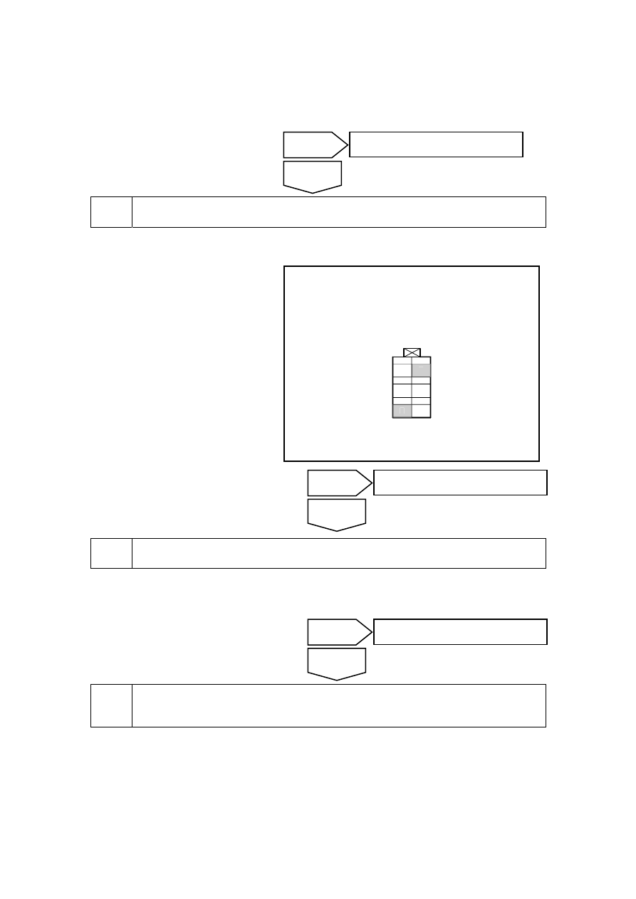


(a)  Replace the left front door lock motor assembly and refer to 11.7.7.1 "Replacement of Left 

Front Door Lock Assembl". 

Lock by a key to confirm whether the electric door lock normally locks. 


Inspect the fastener switch. 


(a) Dismantle central control door 

lock button. 

(b)  Press central control door lock 

button to carry out lock action, 
meanwhile use multimeter to 
measure resistance between wire 
harness connector IP29 terminal 
No.3 and No.4 of lock switch. 

Standard resistant value :is less than 
1Ω 

Confirm if the resistance conforms to 
standard value. 

NL11-2206b

1

4

5

6

2

3

IP29 闭锁器开关线束连接器

3

4


Replace the lock switch. 

(a)  Replace lock switch, refer to 11.7.7.4 lock switch replacement. 

Lock by a central door lock button to confirm whether the electric door lock normally locks. 


Inspect the circuit between the BCM wire harness connector IP50 and the left front door 
motor assembly wire harness connector DR04. 


Yes 

The system is normal. 

No 

Yes 

Go to step 8 

No 

Yes 

The system is normal. 

No 

IP29fastener switchharness 

connector 

2439

(a)  For dismantling of BCM wire 

harness connector, refer to 
11.8.8.1 Replacement of BCM. 

(b)  Dismantle left front door lock 

motor assembly harness 
connector, Refer to11.7.7.1 Left 
front door lock assembly 
replacement. 

(c) Use  multimeter  to  measure 

resistance between BCM wire 
harness connector IP50 terminal 
No. 37 and left front door motor 
assembly wire harness connector 
DR04 terminal No. 8. 

Standard resistant value : is less than 
1Ω 

NL11-2208b

IP50 车身控制模块线束连接器4

1

2

3

4

5

6

7

8

9 10 11 12 13 14 15 16 17 18 19 20

21 22 23 24 25 26 27 28 29 30 31 32 33 34 35 36 37 38 39 40

37

Confirm if the resistance conforms to 
standard value. 

NL11-2207b

1

2

5

6

7

8

9

10

3

4

DR04 左前门锁电机线束连接器

8


Repair the open circuit fault between the BCM wire harness connector IP50 and the left 
front door motor assembly wire harness connector DR06. 

(a)  Make sure that the fault of circuits of BCM wire harness connector IP50 terminal No. 37 and 

circuits corresponding to left front door motor assembly wire harness connector DR04 
terminal No. 8 are repaired. 

Confirm whether the electric door lock is working correctly. 


10 

Inspect the voltage of the terminal No. 6 of BCM wire harness connector IP48. 

Yes 

The system is normal. 

No 

Yes 

Go to step 10 

No 

IP50 body control module harness 

connector4 

DR04 left frontdoor lock motor 

harness connector 

2440


(a)  Use mechanical key or central 

control button to conduct unlock 
action, meanwhile use multimeter 
to measure voltage of BCM wire 
harness connector IP48 terminal 
No. 6. 

Standard voltage: 11-14 V 

Confirm if the voltage conforms to 
standard value. 

NL11-2209b

IP48 车身控制模块线束连接器2

1 2 3

4 5 6

7 8 9

10 11 12 13

6


11 

Replace the BCM 

(a)  Replace BCM and refer to replacement of BCM in 11.8.8.1. 

Confirm whether the electric door lock is working correctly. 


12 

Repair the open circuit between the BCM wire harness connector IP48 and the electronic 
door lock assembly wire harness connector motor terminal. 

(a)  Make sure that the fault of circuits of BCM wire harness connector IP48 terminal No. 10   

and circuits corresponding to each electric door lock assembly wire harness connector motor 
are repaired. 

Confirm the completion of repair. 


13 

The system is normal. 

Next 

Yes 

The system is normal. 

No 

Yes 

Go to step 12 

No 

IP48body control module harness 

connector2 

2441


11.9.6.6 Mechanical key. central control lock switch can not lock. unlock central control 
door lock 

Circuit diagram: 

NL11-2198b

8 IP49

POS LAMP

LICENSE

CDL

LOCK

CDL

UN LOCK

DOL

UN LOCK

TALL CATE

UNLOCK

TALL

CATE AJAR

DOL

LOCK

DR

UNLOCK

DOOR

KEY LOCK

KEY

UNLOCK

DOOR

LOCK

GND

P-DOOR

4 IP50 24 IP50 10 IP48

4

IP+B

15A

IF

04

闭锁器

开关

右前
门锁
电机

右后
门锁
电机

左后
门锁
电机

后背门门锁电机

驾驶员

门锁电机

IP48

5

BCM

IP48

4

SO

4

3

1

3

3

15 IP49

3 IP48 6 IP48

16 IP49 37 IP50 2 IP48

M

M

M

7 DR04

8 DR04

9 DR04

2

SO

43

2

DR0

4

4

DR0

4

SO

4

3

1

SO

43

DR14

DR14

5 IP29

1

4

IP29

4

IP29

3 IP29

2

4

M

DR35

DR35

1

3

M

DR25

DR25


Diagnostic steps: 

Inspect super-locking the key through the remote control key. 

A.  Check whether super locking can be triggered with the remote control key. 


Inspect the possible fault of the remote control anti-theft system. 

A.  Inspect and repair the remote anti-theft system for potential malfunction. 

Confirm whether the electric door lock is normal super-locking. 

Yes 

Go to step 3 

No 

Fastener 

switch 

R

ight

 front

door 

lo

ck

 m

oto

R

ight

 reardoo

lo

ck

 m

oto

Left rear d

oor 

lo

ck

 m

oto

Rear back-door 

door lock motor

Driver door 

lock motor 

2442


содержание   ..  609  610  611  ..