Geely Emgrand X7. Manual part - 520


  Главная      Geely     Geely Emgrand X7 - Manual


поиск по сайту            


содержание   ..  519  520  521  ..


Geely Emgrand X7. Manual part - 520
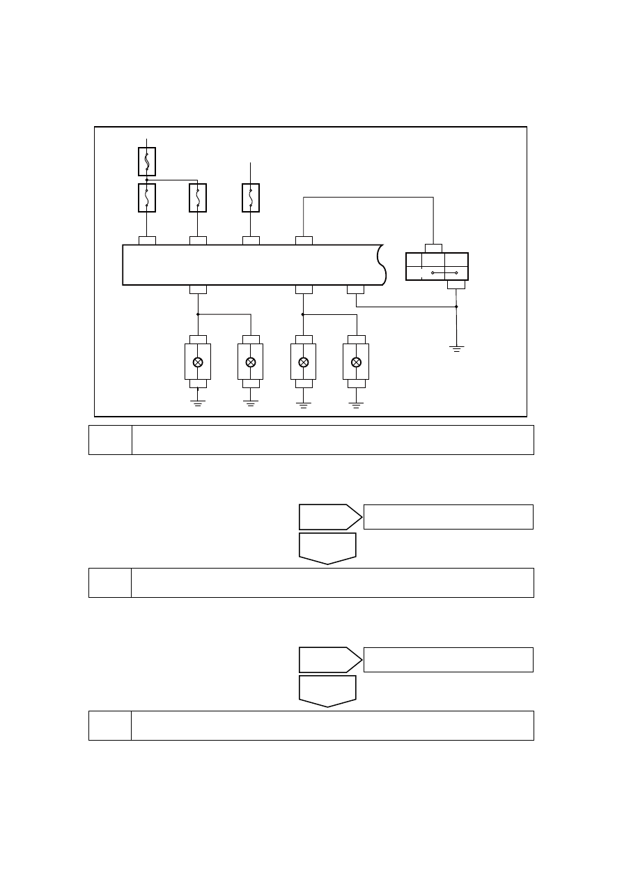


11.4.7.5 Position lamp inoperation 

System diagram: 

NL11-2054b

CA12

CA12

9 CA18

5

9

5

CA18

SO24

SO24

1 IP49

BATT

P-SMALL

LAMP

IG

LH-LAMP

POSITION

LAMPSW

RH-LAMP

BATT

GND

1 IP48

38 IP50

26 IP50

IP49

11

14 IP42

20

10

IP49

IP49

2

SO31

3

2

3 SO31

IG1

BAT

位置

灯光组合开关

16 IP42

15A

IF06

10A

IF05

10A

IF35

30A

E

F

24

左前组合
大灯
(位置灯)

右前组合
大灯
(位置灯)

右后组合
大灯
(位置灯)

左后组合
大灯
(位置灯)

BCM

OFF


Inspect the left front or right front position lamp bulb. 

A.  Dismantle the left front or right front position lamp bulb. 

Is the bulb filament blown? 


Replace Left front or right front position lamp bulb with fault 

A.  Replace the faulty left front or right front position lamp bulb. 

Confirm if the position lights are working properly. 


Check the fuse IF05. 

A.  Check whether the fuse IF05 is blown. 

Fuse Rating: 10A 

Confirm whether the fuses are blown. 

Yes 

The system is normal. 

No 

No 

Go to step 3 

Yes 

Lighting 
combination 
switch 

Position

Left front 
combinatio
n headlamp 
(position 
lamp) 

Right front 
combinatio
n headlamp 
(position 
lamp) 

Right 
rearcombin
ation 
headlamp 
(position 
lamp) 

Left rear 
combination 
headlamp 
(position 
lamp) 

2079


Check the fuse IF05 circuit. 

A.  Inspect the fuse IF05 short circuit malfunction. 

B.  Repair the circuits, Confirm that there are no short circuits. 

C.  Replace the fuses with rated current. 

Confirm if the position light is working correctly. 


Inspect the grounding voltage of the terminal No. 10 and 20 of BCM wire harness 
connector IP49. 


(a)  Turn on position lamp, and 

measure voltage between BCM 
wire harness connector IP49 
terminal No. 10 and terminal No. 
20. 

Standard voltage: 11-14 V 

Confirm if the voltage conforms to 
standard value. 

NL11-2055b

1

2 3

4 5 6

7

8 9 10

11 12 13 14 15 16 17 18 19 20

IP49 车身控制模块线束连接器3

10

20


Repair the circuit between the BCM wire harness connector IP49 and the position lamp. 

(a)  Inspect, repair or replace circuit between BCM wire harness connector IP49 and position 

lamp. 

Confirm if the position light is working correctly. 

Yes 

Go to step 9 

No 

Yes 

The system is normal. 

No 

No 

Go to step 5 

Yes 

IP49body control module harness 

connector3 

2080


Inspect whether it is communicated among the terminal No. 5 of the position lamp 
CA12/18, the terminal No. 3 of SO24/31 and the body grounding. 


(a)  Inspect and repair open-circuit 

between headlamp wire harness 
connector CA12/18 terminal No. 
5 and vehicle body grounding. 

(b)  Inspect and repair open-circuit 

fault between rear combined 
lamp wire harness connector 
SO23/31 terminal No. 3 and 
vehicle body grounding. 

Confirm if the position light is 
working correctly. 

NL11-2056b

9

6

5

1

2

3

4

7

8

CA12/CA18 前组合大灯线束连接器

5


NL11-2057b

1

2

6

3

4

5

SO24/SO31 后组合灯线束连接器

3


Inspect the communication between the terminal No. 14 of the combination switch IP42 
and the terminal No. 26 of the BCM wire harness connector IP50. 


Yes 

The system is normal. 

No 

Yes 

The system is normal. 

No 

CA12/CA18 front combination headlamp 

harness connector 

SO24/SO31 rear combination lamp 

harness connector 

2081

(a)  Inspect and repair open-circuit 

between combined switch IP42 
terminal No. 14 and BCM wire 
harness connector IP50 terminal 
No. 26. 

Confirm if the position light is 
working correctly. 

NL11-2058b

1

9

2

3

4 5

6

7

8

14 15 16 17

10

11 12 13

IP42 灯光组合开关线束连接器

14


NL11-2059b

1

2

3

4

5

6

7

8

9 10 11 12 13 14 15 16 17 18 19 20

21 22 23 24 25 26 27 28 29 30 31 32 33 34 35 36 37 38 39 40

IP50 车身控制模块线束连接器4

26


Inspect the resistance between the terminal No. 16 of the light combination switch wire 
harness connector IP42 and the body grounding. 

(a)  Measure resistance between light combined switch wire harness connector IP42 terminal No. 

16 and vehicle body grounding. 

Standard resistance: less than 1 Ω 

Confirm if the resistance conforms to standard value. 


10 

Replace lighting combination switch, Refer to 11.3.8.1 lighting combination switch 
replacement  . 

No 

Repair ground harness. 

Yes 

Yes 

The system is normal. 

No 

IP42 lighting combination switchharness 

connector 

IP50body control module harness 

connector4 

2082


содержание   ..  519  520  521  ..