Geely Emgrand X7. Manual part - 456


  Главная      Geely     Geely Emgrand X7 - Manual


поиск по сайту            


содержание   ..   451  452  453  454  455  456  457  ..


Geely Emgrand X7. Manual part - 456
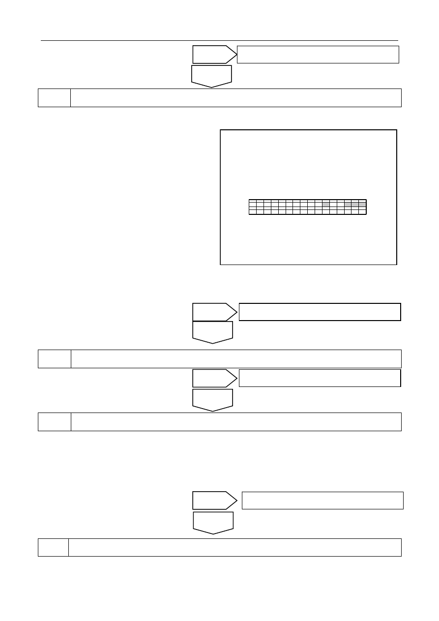


Check the harness (instrument cluster assembly power supply, ground). 


A.    Disconnect the battery negative cable and wait for 

at least 90s. 

B.   Disconnect the connector from the combination 

instrument assembly. 

C.    Connect the battery negative cable and wait for at 

least 2s. 

D.    Turn the ignition switch to ON (IG). 

E.   Measure the voltage between terminals No.1 and 

No.2 of IP01 and the body ground respectively 
with a multimeter. 

Standard Voltage: 11-14 V   

F.    Turn the ignition switch to the OFF position. 

IP01组合仪表线束连接器

16

1

2

3

4

5

6

7

8

9

10

11

12

13

14

15

17

32 31 30 29 28 27 26 25 24 23 22 21 20 19 18

NL09-2103b

G.    Measure the resistance between terminals No.3 and No.6 of connector IP01 and the body ground respectively 

with a multimeter. 

Standard Resistance: Less than 1 Ω 


Inspect whether CAN bus communication is faulty. 

Check CAN bus integrity 


Replace the instrument cluster assembly. 

A.    Replace the combination instrument. Refer to 11.6.7.1 Replacement of Combination Instrument Assembly. 

B.    Connect the battery negative cable and wait for at least 2s. 

C.    Turn the ignition switch to ON (IG). 

D.    Check the airbag warning lamp condition and whether ACU warning lamp is continuously lightening after 

going out 


A.  Turn the ignition switch to ON position, observe the warning lamp status to confirm that the system is 

normal. 

The system is normal. 

Yes 

No 

Properly connect the connector. Go to step 6 

Yes 

No 

Repair or replace the harness. Go to step 6 

Yes 

No 

The system is normal. 

Yes 

No 

Repair or replace the harness. Go to step 6 

IP01 combination instrument harness 

connector


1823


B.    Use a tester to check whether there is a historical failure and clear the historical faults. 


9.2.6.6 Relevant DTC Code Diagnosis 

Collision Sensor Malfunction 

Note: This manual is only for the left front wheel speed sensor fault diagnosis, other sensor diagnostic methods 
are similar. Please refer to the F.L. Wheel Speed Sensor Fault Diagnosis. 

F.L. Collision Sensor Malfunction 

Diagnostic Trouble 

Code (DTC) 

Descriptions Trouble-shooting 

Method 

B105100 

F.L. Collision Sensor Circuit Open 

1. Turn the ignition switch to OFF, and 
disconnect the battery negative cable and wait 
for 90s. 

The above, reconnect the battery negative cable.

2. Measure the resistance between the collision 
sensor harness connector and the ground. 

B105300 

F.L. collison sensor internal fault. 

Replace the sensor; refer to 9.2.7.7 Replacement 
of Front Collision Sensor. 

B105400 

F.L. Collision Sensor Communication 

Error 

Check whether the sensor pin signaling terminal 
and the airbag control module pin are connected 
properly. 

If the connection is not correct, replace the 
harness. 

B105500 

F.L. Collision Sensor Sampling Error

Replace the sensor; refer to 9.2.7.7 Replacement 
of Front Collision Sensor. 

Circuit diagram: 

Refer to 9.2.6.4 Circuit Diagram in Warning Lamp Always On. 

Diagnostic Steps: 

Check the harness (Airbag Electronic Control Unit - power supply, Ground). 


A.  Disconnect the battery negative cable, turn the 

ignition switch to OFF position and wait for 90 
seconds. Pull down the connector from the airbag 
control module. 

B.  Connect the battery negative cable and wait for at 

least 2s . 

C.    Turn the ignition switch to ON (IG). 

D.    Measure the voltage between terminal No.30 of 

harness connector IP15 and vehicle body ground 
with a multimeter. 

Standard Voltage: 11-14 V 

E.  Turn the ignition switch to OFF position . 

1

2

3

4

5

6

7

8

9 10 11 12 13 14 15 16 17 18 19 20 21 22 23 24 25

26 27 28 29 30 31 32 33 34 35 36 37 38 39 40 41 42 43 44 45 46 47 48 49 50

IP15安全气囊控制模块线束连接器

NL09-2102b

IP15airbag control module harness 

connector


1824


F.    Measure the resistance between terminal No.5 of harness connector IP15 and vehicle body ground with a 

multimeter. 


Standard Resistance: Less than 1 Ω 

Inspect the harness connector. 

A. Disconnect the airbag control module harness connector IP15. 

B. Disconnect the left front collision sensor harness connector CA11. 

Are the two harness connectors normal? 


Inspect the left front collision sensor harness (open circuit). 


A.    Measure the resistance between terminal No.36 of 

IP15 and terminal No.1 of CA11 with a 
multimeter. 

B.    Measure the resistance between terminal No.11 of 

IP15 and terminal No.2 of CA11 with a 
multimeter. 

Standard Resistance: Less than 1 Ω 

Is the resistance at a specified value? 

1

2

3

4

5

6

7

8

9 10 11 12 13 14 15 16 17 18 19 20 21 22 23 24 25

26 27 28 29 30 31 32 33 34 35 36 37 38 39 40 41 42 43 44 45 46 47 48 49 50

IP15安全气囊控制模块线束连接器

NL09-2104b


2

1

CA11左前碰撞传感器线束连接器

NL09-2105b

Yes 

No 

Inspect the fuses, repair or replace the harness. 

No 

Yes 

Replace the harness connectors. 

CA11 left front collision sensor harness 

connector


IP15airbag control module harness 

connector


1825


Inspect the left front collision sensor harness (whether there ia short circuit between lines). 

A.  Measure the resistance between terminals No. 1 and No. 2 of connector CA11 with a multimeter. 

Standard Resistance: 10 kΩ or higher 

Is it a Standard resistance? 


Check the left front collision sensor harness (whether the circuit is short to ground). 

A.    Measure resistance between terminal No.1 of CA11 and the vehicle body ground with a multimeter. 

B.    Measure resistance between terminal No.2 of CA11 and the vehicle body ground with a multimeter. 

Standard Resistance: 10 kΩ or higher 

Is it a Standard resistance? 


Check the left front collision sensor harness (short to power supply). 

A.    Connect the battery negative cable and wait for at least 2s. 

B.    Turn the ignition switch to ON (IG). 

C.  Measure voltage between terminals No.1 and No.2 of CA11 and the body ground respectively with a 

multimeter. 

Standard Voltage: Less than 1 V 

Is it a Standard resistance? 


Replace the left front collision sensor. 

A.    Disconnect the battery negative cable and wait for at least 90s. Refer to 2.12.6.1 Battery Cable Disconnection 

and Connection Procedures. 

B.    Replace left collision sensor, refer to 9.2.7.7 Replacement of Front Collision Sensor. 

Yes 

No 

Replace the harness 

Yes 

No 

Replace the harness 

Yes 

No 

Replace the harness 

Yes 

No 

Replace the harness 

1826


содержание   ..   451  452  453  454  455  456  457  ..