Geely Emgrand X7. Manual part - 127


  Главная      Geely     Geely Emgrand X7 - Manual


поиск по сайту            


содержание   ..   124  125  126  127  128  ..


Geely Emgrand X7. Manual part - 127
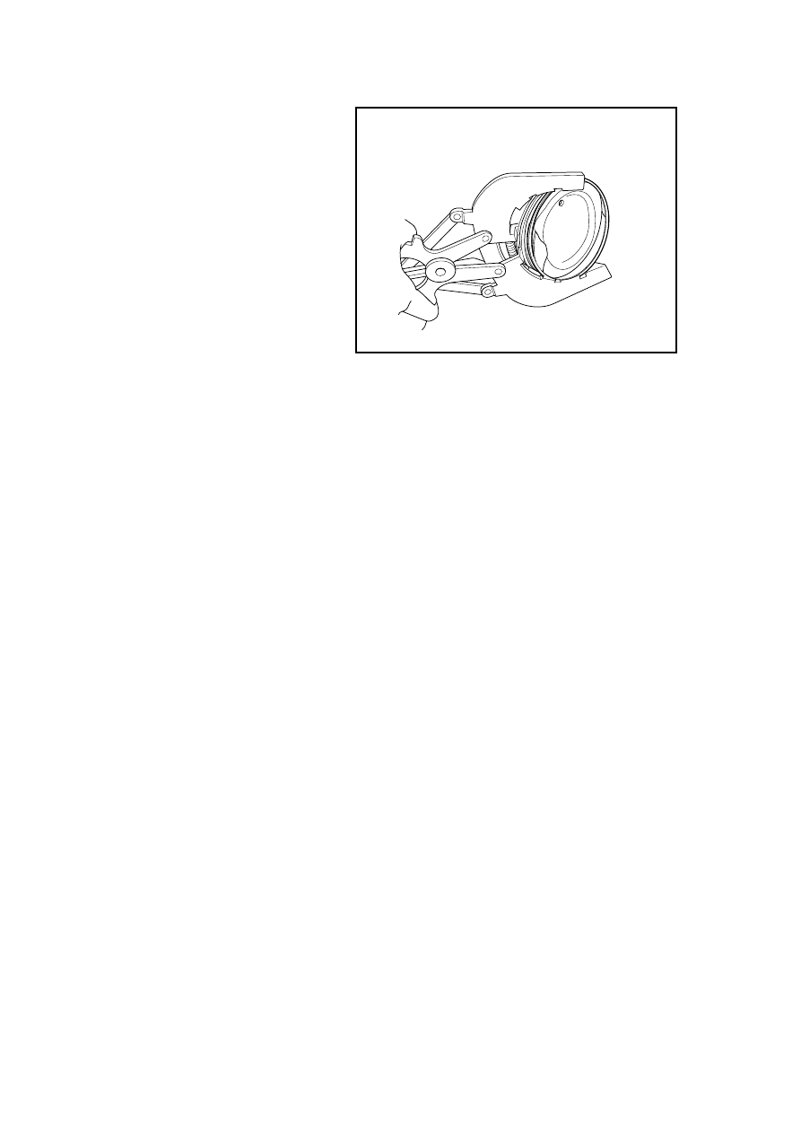


9.  Install first air ring. 

Note: The side of the piston ring with 
marker should face the piston top. 

10. Apply the engine oil to the 

connecting rod bearings and 
install the connecting rod journal 
and the bearing cap. 

11.  Install the connecting rod to the 

crankshaft. Inspect whether the 
bearing clearance is acceptable. 
Refer to 2.6.1.2 "Mechanical 
System Specification". 

Standard Value 

0.0200.044 mm(Metric) 

0.00070.0017 in (English system) 

13.  Install and inspect the qualified 

piston connecting rod 
components. 

FE02-0286b

507

2.6.8.21 Valve Clearance Adjustment 

1.  Dismantle the plastic shield of engine. Refer to 2.6.8.1 Replacement of Plastic Shield of 

Engine. 

2.  Refer to 2.10.7.3 "Replacement of Ignition Coil" to dismantle the ignition coil. 

3.  Refer to 2.6.8.2 "Replacement of Cylinder Hood Cover" to dismantle the cylinder hood 

cover. 

4.  Refer to 2.6.8.9 "Replacement of 

Timing Chain Shroud" to 
dismantle the timing chain 
shroud and rotate the crankshaft 
making cylinder No.1 at 
compression TDC position. 

5.  Inspect valve clearance. Use the 

plug gage to measure valve 
clearance value, as arrows shown 
in the graphic and record the 
valve location and tolerance that 
exceeds the tolerance. 

Valve clearance standard value 
(Cold): 

Air intake 

0.25±0.03mm 

Exhaust: 0.3±0.03mm 


FE02-3060b

6.  Rotate the crankshaft one circle 

(360 °), making the cylinder No. 
4 stop at the compression TDC 
position. Measure the valve 
clearance as arrow pointed in the 
graph and record the clearance. 

FE02-3061b

508

7.  Use a jack to support the engine. 

Dismantle the timing chain. 
Refer to 2.6.8.10 "Replacement 
of Timing Chain" 

8.  Refer to 2.6.8.12 “Replacement 

of Camshaft” to dismantle the 
camshaft. 

9.  Remove the valve lifter that 

exceeds the tolerances. Use 
outside diameter micrometer to 
measure the thickness, according 
to the following formula 
calculate the thickness of the new 
valve lifters. 

FE02-0289b

Intake: A=B+C-0.23 mm(0.01in)   

Exhaust: A=B+C-0.32mm(0.13in) 

10.  Selected new valve lifters must be as close as possible to the calculated values. For 

specifications. Refer to 2.6.1.3 Specification Table for Tappet Rods of Intake and Exhaust 
Valves for the thickness of the tappet rod of valve. 

11.  Based on the measurement, according to 2.6.1.4 Selection Table for Tappet Rod of Exhaust 

Valve, choose the tappet rod of valve to meet the specification. 

12.  Install intake and exhaust camshafts. 

13.  Install timing chain 

14.  Install the timing chain cover. 

15.  Install the ignition coil. 

16.  Install the plastic shield of engine. 

Thickness of new valve lifter 

Thickness of old valve lifter 

C Measured 

Valve 

Clearance 

509

2.6.8.21 Replacement of Crankshaft Rear Oil Seal 

Dismantlement Procedure 

1.  Refer to 2.6.8.17 “Replacement 

of Flywheel” to dismantle the 
flywheel. 

2.  Dismantle the crankshaft rear oil 

seal. 

Note: Be careful not to damage the 
crankshaft journal during 
dismantlement.
 

GC02-0086c

Installation Procedure: 

1.  Use a special tool to install the 

crankshaft rear oil seal. 

2.  Install the flywheel. 


510


содержание   ..   124  125  126  127  128