Geely Emgrand X7. Manual part - 119


  Главная      Geely     Geely Emgrand X7 - Manual


поиск по сайту            


содержание   ..   114  115  116  117  118  119  120  ..

Geely Emgrand X7. Manual part - 119
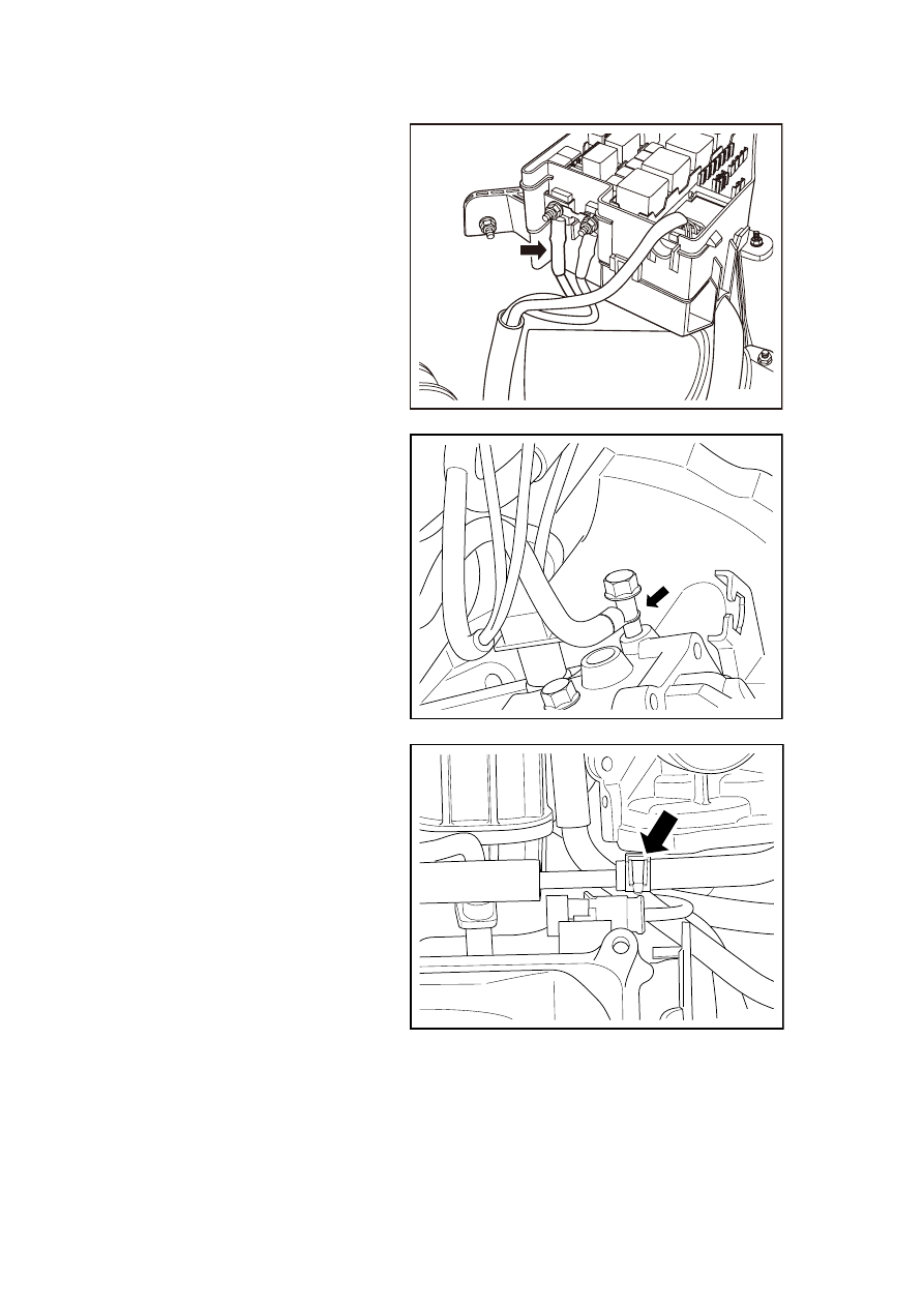


18. Dismantle the engine wiring 

harness to the engine cabin 
junction box connecting cables 
and connectors. 

NL02-0181b

19.  Dismantle battery negative cable 

gearbox shell grounding point. 

NL02-0005c

20.  Dismantle the fuel pipe. 

NL02-0006c

475

21. Dismantle the canister vacuum 

tubes. 

NL02-0007c

22.  Dismantle gear shift lever cable. 

GC03-0036b

23.  Dismantle the heater intake and 

outlet pipes. 

NL02-0186b

476

24.  Dismantle the front wheels. 

25.  Lifting and Jacking the Vehicle 

Warning: Refer to Warning on 
Vehicle Lifting and Jacking in 
Warnings and Precautions. 

26. 

Dismantle the gearbox oil 
discharge bolts until all the 
gearbox oil is discharged and 
reinstall. Refer to 3.3.6.1 
Gearbox Oil Level Inspection. 

27. Dismantle the power steering 

gear tie rod lateral pin bolts. 

Warning: Before remove the 
steering lateral pin bolt, remove the 
key from the ignition switch first 
and turn the steering wheel to lock 
position. Otherwise it will damage 
the airbag clock spring.
 

NL02-0187b

28.  Refer to 12.6.4.3 "Replacement 

of Longitudinal Beam of Front 
Suspension" and 12.6.4.4 
"Replacement of Front 
Subframe" to dismantle the 
longitudinal beam of front 
suspension, subframe and 
associated connectors. 

29. Dismantle left and right drive 

shaft. Refer to 5.3.4.2 
Replacement of drive shaft. 

30. Place a mobile working table 

under the engine assembly to 
lower and support the powertrain 
assembly. 

Warning: Make sure solid contact 
between the working table and the 
powertrain, otherwise it will result 
in human injury.
 

NL03-0009c

477

31. Dismantle the engine right 

suspension assembly . 

32. Dismantle the gearbox left 

suspension assembly . 

33. Lift the vehicle slowly to 

separate powertrain from the 
frame . 

Note: In the lifting process, avoid the 
powertrain assembly tilt on the 
working table. Pay attention to the 
powertrain and vehicle body 
interference. 

34.  Use an engine lifting device to 

support the engine and then 
separate the engine and the 
gearbox. Refer to 3.3.6.3 
Replacement of Gearbox. 

NL02-0008c

Installation Procedure: 

1.  Use the engine lifting device to support the engine and then connect the engine assembly and 

the gearbox assembly. 

2.  Place the powertrain assembly on the mobile working table, lift the vehicle and move the 

working table so the powertrain assembly moves back into the vehicle body frame. 

3.  Slowly lower the vehicle. Pay attention in the lowering process; do not interfere with the 

vehicle body frame. 

Note: Make sure solid contact between the working table and the powertrain, otherwise it will 
result in personal injury. 

4. Install the engine right 

suspension assembly. 

Torque :45Nm (Metric) 33 . 3lb-ft 
(English system) 

5. Install the gearbox left 

suspension assembly. 

Torque :50Nm (Metric) 37lb-ft 
(English system) 

6.  Lifting and Jacking the Vehicle 

7.  Install the left and right drive 

shafts. 

8.  Install the longitudinal beam of 

front suspension and front 
subframe. 

NL02-0008c

478


содержание   ..   114  115  116  117  118  119  120  ..