Geely Emgrand X7. Manual part - 102


  Главная      Geely     Geely Emgrand X7 - Manual


поиск по сайту            


содержание   ..   100  101  102  103  ..


Geely Emgrand X7. Manual part - 102


5 Inspect 

EAS 

Coil 


(a) Disconnect electronic Anti-theft 

coil harness connector. 

(b) Use multimeter to measure 

resistance of coil. 

Standard Resistance Value: 5 Ω at 
room temperature 20°C(68 ºF) 

Is EAS coil resistance specified value?

NL02-2195b

1

2

3

4

5

6

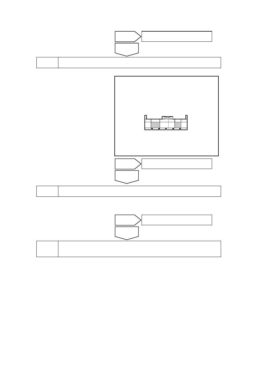
IP43 电子防盗天线线束连接器

2

5


Replace electronic Anti-theft coil. 

(a)  Refer to 2.5.8.1 “Replacement of EAS coil” to replace the EAS coil. 

Can the vehicle start? 


Inspect circuit between EAS coil harness connector and engine anti-theft system 
control module harness connector. 

(a)  Measure the resistance between the anti-theft coil harness connector IP43 terminal No.2 and 

engine anti-theft system control module wiring harness connector IP25 terminal No.2 with a 
multimeter to determine circuit continuity. 

Standard Resistance: Less than 1 Ω 

(b)  Measure the resistance between the anti-theft coil harness connector IP43 terminal No.5 and 

engine anti-theft system control module wiring harness connector IP25 terminal No.1 with a 
multimeter to determine circuit continuity. 

Standard Resistance: Less than 1 Ω 

Whether resistance meet standard or not? 

Yes 

The system is normal. 

No 

Yes 

Go to step 7 

No 

Yes 

The system is normal. 

No 

IP43electric immobilizer antenna harness 

connector 

407


Repair circuit between EAS coil harness connector and engine anti-theft system 
control module harness connector. 

(a)  Repair the open circuit fault between the electric anti-theft coil wiring harness connector IP43 

terminals No.2 and engine control module wiring harness connector IP25 terminal No.2 to 
determine circuit continuity. 

(b)  Repair the open circuit fault between the electric anti-theft coil wiring harness connector IP43 

terminals No.5 and engine control module wiring harness connector IP25 terminal No.1 to 
determine circuit continuity. 

Can the vehicle start? 


Inspect the serial communication circuit between the engine anti-theft system control 
module and engine control module. 

(a)  Inspect the serial communication circuit open between engine anti-theft system control 

module wiring harness connector IP24 terminals No.5 and engine control module harness 
connector EM01 terminal No.46, to determine the continuity. 

Standard Resistance: Less than 1 Ω 

(a)  Inspect the serial communication circuit open between engine anti-theft system control 

module wiring harness connector IP24 terminals No.8 and engine control module harness 
connector EM01 terminal No.75, to determine the continuity. 

Standard Resistance: Less than 1 Ω 

Does the resistance conform to standard value? 


10 

Repair serial communication circuit between engine anti-theft system control module 
and engine control module. 

(a)  Repair the serial communication open circuit between engine anti-theft system control 

module connector IP24 terminal No.5 and the engine control module connector EEM01 
terminal No.46. 

(b)  Repair serial communication circuit open resistance between engine anti-theft system control 

module wiring harness connector P24 terminals No.8 and engine control module harness 
connector EM01 terminal No.75. 

Can the vehicle start? 

Yes 

Intermittent fault. refer to2 . 2 . 7 . 3 
intermittent fault inspection 

No 

Yes 

The system is normal. 

No 

Yes 

Go to step 9 

No 

408


11 

Replace anti-theft system control module. 

(a)  Replace anti-theft system control module and refer to 2.2.8.1 "Replacement of Engine 

Control Module". 

(b)  Refer to 2.5.7.9 "Replacement of Programming after Anti-theft Module" to carry out engine 

anti-theft system programming procedures. 


12 

Replace engine control module. 

(a)  Replace the engine control module and refer to 2.2.8.1 "Replacement of Engine Control 

Module". 

(b)  Refer to 2.5.7.10"Replacement of Programming after ECM" to carry out engine anti-theft 

system programming procedures. 

Confirm the repair has been completed. 


13 

The system is normal. 

Next 

Yes 

The system is normal. 

No 

Yes 

The system is normal. 

No 

409

2.5.8 Removal and installation 

2.5.8.1 Replacement of EAS Coil 

Dismantlement Procedure 

Warning: Refer to "Warning on 
Battery Disconnection" in 
"Warnings and Precautions". 

1.  Disconnect the battery negative 

cable. Refer to 2.12.6.1 Battery 
Cable Disconnection/Connection 
Procedures. 

2.  Turn the steering wheel and 

dismantle the upper and lower 
steering column shield panel 
retaining screws. 

NL02-0031b

3.  Dismantle the lower steering 

column shield screw. 

4.  Remove the steering column 

upper and lower shield panels. 

NL02-0032b

5. Disconnect  the  electronic 

anti-theft wiring harness coil 
connector. 

NL02-0038b

410


содержание   ..   100  101  102  103