Geely Emgrand X7. Manual part - 42


  Главная      Geely     Geely Emgrand X7 - Manual


поиск по сайту            


содержание   ..  40  41  42  43  ..


Geely Emgrand X7. Manual part - 42


(b)  Disconnect VVT solenoid valve harness connector EM13. 

(c)  Rotated ignition switch to ON position . 

(d)  Test EM13 connector terminal A with a multimeter. 

Standard Voltage: 11-14V 

(e) Connect VVT solenoid valve harness connector EM13. 


Step 3 

Inspect VVT solenoid valve control circuit. 


(a)  Rotated ignition switch to OFF 

position . 

(b) Disconnect VVT solenoid valve 

harness connector EM13. 

(c) 

Disconnect ECM harness 
connector EM01. 

(d)  Use multimeter to measure the 

resistance between VVT solenoid 
valve harness connector EM13 
terminal No.B and ECM harness 
connector EM01 terminal 43. For 
the Standard Value. Refer to the 
table below. 

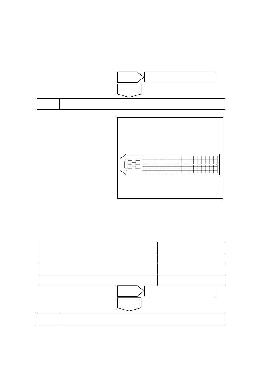
ECM线束连接器

EM01

1

2

4

5

3

81

63

44

25

6

62

43

24 23 22 21 20 19 18 17 16 15 14 13 12 11 10

9

8

7

26

42 41 40 39 38 37 36 35 34 33 32 31 30 29 28 27

45

46

61 60 59 58 57 56 55 54 53 52 51 50 49 48 47

64

65

66

80 79 78 77 76 75 74 73 72 71 70 69 68 67

NL02-0033c

(e)  Use multimeter to measure the resistance between VVT solenoid valve wiring harness 

connector EM13 terminal B and the ground. For the Standard Value. Refer to the table below. 

(f)  Turn the ignition switch to ON position, (Note: At this point EM01, EM13 connectors must 

be disconnected) Measure voltage between VVT solenoid valve wiring harness connector 
EM13 terminal B and a reliable ground with a multimeter. the Standard Value is in the table 
below. 

Test Connection 

Standard Value 

Resistance Between EM13(B) and EM01 (43) 

Less than 1 Ω 

Resistance Between EM13 (B) and Ground 

10 kΩ or higher 

Voltage Between EM13 (B) and Ground 

Less than 0 V 


Step 4 

Inspect the ECM Power Supply Circuits. 

(a)  Inspect whether ECM power supply circuit is normal. 

(b)  Inspect whether ECM ground circuit is normal. 

No 

Repair or replace harness connector 

Yes 

No 

Inspect whether circuit between EM09 solenoid valve 
harness connector terminal No.A and main relay terminal 
No.3 is open or short to ground.

Yes 

ECMharness connectorEM01 

167


Step 5 

Replace ECM. Refer to 2.2.8.1 Replacement of Engine Control Module. 


Step 6 

Carry out the crankshaft position sensor learning, refer to 2.2.7.11 “Crankshaft 
Position Sensor (CKP) Learning. 


Step 7 

Use fault diagnosis tester to confirm if DTC is stored again . 

(a)  Connect the fault diagnosis tester to the diagnostic interface. 

(b)  Turn ignition switch to ON position. 

(c)  Clear DTC code. 

(d)  Start and run the engine at idle speed to warm up the engine for at least 5 min. 

(e)  test the vehicle on the road for at least 10 min. 

(f)  Read control system DTC code again. Verify that the system has no DTC code output. 


Step 8 

Troubleshooting 

5. Maintenance 

guide 

Refer to 2.2.8.5 Replacement of VVT Solenoid Valve and Filter Cleaning to replace the VVT 
solenoid valve. 

No 

Repair or replace harness connector 

Yes 

Next 

Next 

No 

Repair or replace harness connector 

Yes 

168

2.2.7.18 P0107 P0108 

1. DTC 

description: 

DTC P0107  Manifold air pressure sensor circuit has low voltage or is open 


DTC P0108  Intake Air Pressure Sensor Circuit High Voltage 

Intake Air Manifold Absolute Pressure (MAP) Sensor responds to the pressure changes within the 
intake manifold. Pressure varies according to engine load. The MAP sensor circuit consists of the 
following: 

• 5V 

reference 

voltage 

• 

Low Reference Voltage Circuit 

• Sensor 

Signal 

Circuit 

ECM provides sensor harness connector EM30 terminal No.1 5 V reference voltage through ECM 
harness connector EM01 terminal No.66. And, a low reference voltage through EM01 terminal 
No.76 to EM30 terminal No.4. The sensor provides a signal through EM30 terminal No.2 to ECM 
harness connector EM01 terminal No.54. This signal is related to the intake manifold pressure 
change. When the intake manifold absolute pressure is low, such as at idle or during deceleration, 
ECM detected signal voltage is low. When the intake manifold absolute pressure is high, such as 
the ignition switch turned on with the engine is turned off, or when the throttle is fully open, ECM 
detected signal voltage is high. Sensors are also used to determine the atmospheric pressure. When 
the ignition switch is turned on and the engine is turned off. As long as the engine running with the 
throttle fully open, atmospheric pressure readings will also be updated. ECM monitors sensor 
signals in order to determine whether the voltage is beyond the normal range. 

2.  Conditions For Setting DTC and The Fault Location: 

DTC Code 

DTC Detection Strategy

Conditions For Setting The DTC 
(Control Strategy) 

Fault Locations 

P0107 

Circuit Inspection, Over 
the Minimum Limit 

1. Idle 

2.  When the sensor circuit is 

open or short to ground, the 
sensor signal voltage is 0 

P0108 

Circuit Inspection,over 
the Maximum Limit 

1. Idle 

2.  When the sensor circuit short 

to power supply or a 5 V 
reference voltage 

3.  Sensor A/D initial signal is 

99.6% 

1. Sensor 

Circuit 

2. Sensor 

3. ECM. 


169

3. Circuit 

sketch 


EM01

66

54

EM01 MAP

V5REF2

1

2

进气压力
温度传感器

P

76

EM01 V5RTN2

4

71

EM01 MAT

3

NL02-0034c


4. Diagnostic 

Steps: 

Note: Before carrying out this diagnosis step, observe the data list on fault diagnosis tester and 
analyze the accuracy of the data, as these will help with quick diagnosis. 


Step 1 

Initial Inspection 

Inspect if there are the following conditions: 

(a)  Sensor housing damage, vacuum tubes broken. 

(b) Sensor 

seal 

damage. 

(c)  Sensor loose or improperly installed. 

(d)  Sensor tube blockage. 

Notes:It is not allowed to connect 5 V reference voltage circuit of intake manifold absolute 
pressure sensor and other components of the vehicle, as this will damage the sensors and ECM. 


Step 2 

Measure intake manifold absolute pressure sensor 5 V reference voltage. 


Next 

Next 

Air intake 
pressuretemperature 
sensor 

Engi

ne

 co

ntr

ol mo

dul

170


содержание   ..  40  41  42  43  ..