Geely Emgrand X7. Manual part - 25


  Главная      Geely     Geely Emgrand X7 - Manual


поиск по сайту          


содержание   ..  20  21  22  23  24  25  26  ..


Geely Emgrand X7. Manual part - 25
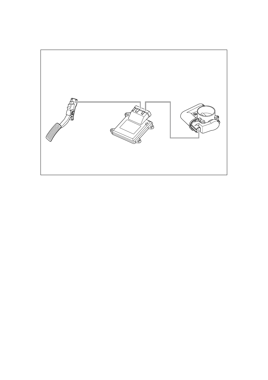


2.2.3 System operating principle 

2.2.3.1 Electronic Throttle Body (ETC) Operating Principle 

油门踏板位置

传感器总成

发动机

控制模块

电子控制

节气门体总成

NL02-2014b


Electronic throttle body assembly must be used dedicatedly to the engine electronic control 
module (ECM) with ETC system-driven feature hardware as the core control element. System 
control software usually uses the computer algorithms mode, basing on the engine torque output 
control. At the same time, due to the cancellation of the traditional mechanical throttle valve 
control of mechanical pull cables, ETC is equipped with a acceleration pedal position sensor (APP) 
with a resistive potentiometer device, in order to provide vehicle handling demand information 
and other information for the driver to control the vehicle to the engine electronic control module 
(ECM). 

Electronic throttle body opening is determined by ECM according to the acceleration pedal control 
input signals. With other engines and vehicles sensor input signals, ECM analyzes the driver's 
intention in advance and calculates the needed engine output power and accordingly adjusts the 
engine throttle opening and fuel supply (injection) amount. At the same time, the electronically 
controlled throttle position sensor can detect the actual throttle opening and send the feedback to 
ECM. ECM then, based on this feedback signal, adjusts the vehicle control parameters. This 
control process ensures that the engine and vehicle work in the ideally controlled conditions. Due 
to the rapid development of modern science and technology, High-Speed ECM can quickly 
analyze the driver's intention and calculate the basic throttle opening parameter values, based on 
the throttle pedal signal, the signal variation and signal change rate. At the same time, ECM 
adjusts and optimizes the throttle opening parameter, based on various sensors input signal status, 
so that the system further calculates the optimum throttle opening control parameters and 
implements the actual throttle control. ECM sends the output control signal to the ETC motor 
drive circuit to open the throttle according to the calculated opening parameter, based on the 
revised throttle opening and pre-determined control strategy. Because of the high speed calculation, 
the system enables smooth engine speed changes under transition engine operating conditions. The 
whole control process only requires a few milliseconds, achieving excellent vehicle performance. 

The application of automotive electronic technology makes it difficult to directly judge the 
electronic drive control throttle valve body assembly diagnosis by conventional visual inspection 
method. In the event of electronic controlled throttle body malfunction, the system needs to 
provide a Jolt-limited function. It allows the driver to drive the vehicle to a repair station for 
repair. 

Accelerator position 

sensor assembly 

Engine control 

module 

Electric control throttle 

body assembly 

99

Jolt-limited control has the following two kinds of control modes 

1.  Jolt-limited control with the system unable to control the engine power 

ECM will limit the engine power output, and the system can not control the throttle opening and 
closing. The throttle opening is automatically adjusted to the system pre-determined position. 

ECM will shut down the engine ignition output. At this time, the ECM internal fault occurs and 
the system can not control the engine torque output. The throttle body adjusts the opening to (zero 
position) off status. The system will fully turn off the ignition control function. 

2.  Jolt-limited control with the system unable to monitor the driver's intention 

ECM will limit the engine power output. At this point, the system loses the ability to determine 
and monitor the driver's intention. In order to prevent damage to the engine, ECM will limit the 
engine power output and lower engine power increment and velocity increment. When braking, 
ECM will adjust the engine speed to idle speed and adjust the throttle opening to the system 
pre-determined position. 

ECM will force the engine working at idle running status. When the system loses the ability to 
determine and monitor the driver's intention, ECM will force the engine working at idle running 
status, and system will work at pre-determined position controlled the idle speed. 

100

2.2.3.2 ECM Controlled Fuel Supply System 

1.  Fuel Pump Control 

When the ignition switch is turned on, the fuel pump will run for 2 s. At this moment, if ECM does 
not detect the engine speed signal, fuel pump stops running. Once the engine rotates, ECM detects 
the engine speed signal and then controls the fuel pump running. 0.6 s after the engine speed 
signal is lost, or the anti-theft device requests to shut down the fuel pump, the fuel pump stops 
running. 

2.  Start-up Fuel Injection Control 

Pre-injection of starting fuel injection control can inject once during the normal starting procedure. 
The pre-injection starts when the following conditions are satisfied: 

Actuation of oil pump relay 

– 

Fuel pump running longer than the accumulation of pressure’s delay time. 

– 

The pre-injection has not yet occurred. 

– 

Once all the above conditions are met, the pre-injection will start in all cylinders at the same 
time. 

3.  Fuel Injection Pulse Width Control 

A. Air-Fuel 

Ratio 

The startup air-fuel ratio, the normal 
startup air-fuel ratio, the air-fuel ratio 
of clearing flooded-cylinder, the 
air-fuel ratio when the engine is 
running, the air-fuel ratio in cooling 
state, the air-fuel ratio in the warm-up 
state, the theoretical air-fuel ratio, the 
power enriched air-fuel ratio, the 
catalytic overheating protection 
air-fuel ratio and the engine 
overheating 

Keep the air-fuel ratio. 

B. Intake 

Manifold 

Absolute 

Pressure 

Intake manifold pressure is read 
directly by the MAP sensor installed 
on the intake manifold. 

C. Volumetric 

Efficiency 

Volumetric efficiency is the ratio of 
actual air flow into the cylinder to the 
ideal air flow. 

充气温度

歧管压力

喷嘴常数

空燃比

喷油脉宽

喷油量计算

空气流量

充气效率

自学习修正

过渡工况
燃油控制

充气温度

电压修正

减速断油

配气相位的

充气效率补偿

FE02-8038b

D.  Valve Timing Volumetric Efficiency 

The valve timing changes affect the engine's volumetric efficiency. The basic volumetric 
efficiency form is set when the valve timing control system has not started to work and the 
camshaft and the crankshaft are at the initial positions. After port timing control system starts to 
operate, system carries out corresponding air charging efficiency compensation to ensure accurate 
calculation of air inlet volume. 

E. Self-Learning 

Air fuel 

ratio

Manifold 

pressure

Inflation 

temperature

Air 

flow 

Charging 

efficiency

Self-learning 

correction

Nozzle 

constant

Injecting 

pulse width

Voltage 

correction 

Charging efficiency 

compensation of 

valve timing 

Decrease 

fuel cut off

Fuel control of 

transient operation

Inflation 

temperature 

Fuel charge 

calculation

101

Self-learning does not amend the changes as the engine running time increases, or the engine and 
vehicle manufacturing errors. 

F.  Close-loop Feedback Correction 

Close-loop feedback correction controls the actual Air-Fuel ratio close to the theoretical Air-Fuel 
ratio through the oxygen sensor feedback signals. 

G.  Transition Condition Fuel Control 

System uses more complex algorithms to establish the fuel evaporation model to calculate 
Air-Fuel mixing conditions, taking into account the engine coolant temperature, intake air 
temperature and engine working condition and the best fuel injection amount. It greatly improves 
fuel control under various transitional working conditions, including sudden 
acceleration/deceleration and other working conditions. 

H.  Protective Fuel Cut-off Control 

When any one of the following conditions is met, the system will stop fuel injection: 

– 

Cutting off when the engine speed is higher than 6,500 rpm and resume fuel supply when the 
engine speed drops below 6,000 rpm. 

– 

When the system detects an ignition system malfunction, it stops the fuel supply. 

–  When the system voltage is more than 18V, the function of electric valve body will be 

limited. 

Mode (Forced idling mode) 

I. 

Basic Fuel Injection Constant 

Whether the basic fuel injection constant indicates the relationship between engine displacement 
and nozzle fuel flow rate. 

J. Battery 

Voltage 

Amendment 

When the battery voltage changes, the voltage will be amended to ensure the correct amount of 
fuel injection. 

102


содержание   ..  20  21  22  23  24  25  26  ..