Geely EC718, EC718RV, EC715, EC715RV. Manual part - 481


  Главная      Geely     Geely Emgrand EC718, EC718RV, EC715, EC715RV. Workshop Manual year 2009


поиск по сайту            


содержание   ..  479  480  481  482  ..


Geely EC718, EC718RV, EC715, EC715RV. Manual part - 481


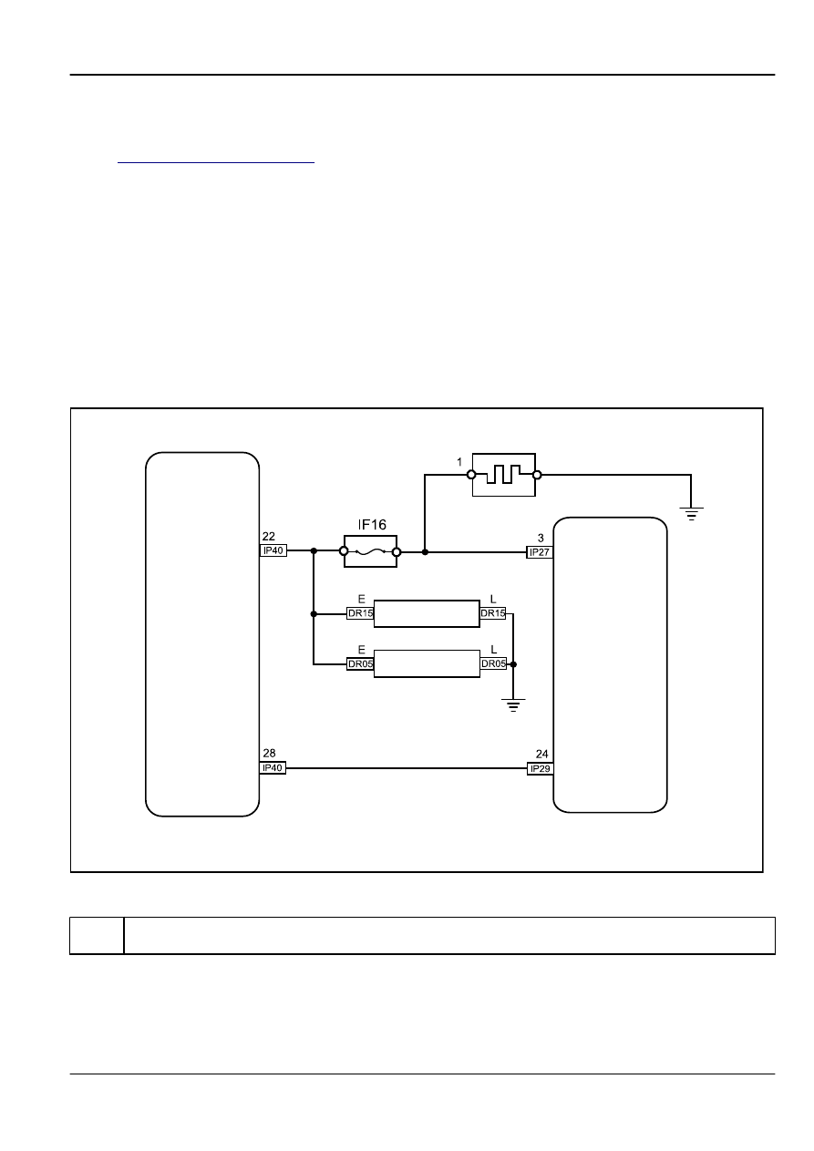
11.12.6 Diagnostic Information and Procedures
11.12.6.1 Diagnosis Description

Refer to 

11.12.2.1


Description and Operation

get familiar with the system functions and operation before start system diagnostics,

so that it will help to determine the correct diagnostic steps, more importantly, it will also help to determine whether the customer
described situation is normal.

11.12.6.2 Visual Inspection

Check installed aftermarket equipment that may affect the defrosting operation.

Check the easy to access system components to identify whether there is a significant damage or a potential malfunction.

If all the defroster are inoperative, check and repair the power supply or ground circuit poor connection, or open circuit.

11.12.6.3 Rear Window Defroster Inoperative

Schematic:

Rear Window Defog

A/C Control Module

Right Outside Rearview 

Mirror Defogger

Left Outside Rearview 

Mirror Defogger

Body Control Module

FE11-6100b

Diagnostic Steps:

Step 1

Use scan tool active test function to check the defroster working status.

(a)

Select as the following sequence: Body Control Module /
active test / rear defroster output control.

Is the rear defroster working properly?

Body Electric

Defrosting

11-437

No

Go to step 6

Yes

Step 2

Check the defrost button.

16
32

15
31

14
30

13
29

12
28

11
27

10
26

9

25

8

24

7

23

6

22

5

21

4

20

3

19

2

18

1

17

A/C Control Panel Harness Connector IP40

FE11-6105b

(a)

Press the defrost button.

(b)

At the same time,test continuity between the air-conditioning
control module harness connector IP40 terminal No.28 and
the body ground with a multimeter.

Test Terminal

Test

Conditions

Continuity

IP40 28 - Body Ground

Release

10 kΩ or higher

IP40 28 - Body Ground

Press

Less than 1 Ω

Is the resistance specified value?

Yes

Go to step 4

No

Step 3

Replace the air-conditioning control panel.

(a)

Replace the air-conditioning control panel. Refer to

8.2.8.1


Air-conditioning Control Panel Replacement

.

Is the rear window defrosting function working correctly?

Yes

System normal

No

Step 4

Check the defrost request signal.

1

2

3

4

5

6

7

8

9 10

20

30

40

19

29

39

18

28

38

17

27

37

16

26

36

15

25

35

14

24

34

13

23

33

12

22

32

11

21

31

Body Control Module 1 Harness 
Connector IP29

FE11-6102b

(a)

Press the defrost button.

(b)

At the same time, test continuity between the BCM harness
connector IP29 terminal No.24 and the ground with a
multimeter.

Test Terminal

Test

Conditions

Continuity

IP29 24 - Body

Ground

Release

10 kΩ or higher

IP29 24 - Body

Ground

Press

Less than 1 Ω

Is the resistance specified value?

Yes

Go to step 6

11-438

Defrosting

Body Electric

No

Step 5

Repair the defrost request signal open circuit.

(a)

Repair the open circuit.

Is the rear window defrosting function working correctly?

Yes

System normal

No

Step 6

Check the BCM defrost power output.

1

2

3

4

5

6

7

8

Body Control Module 3 Harness 
Connector IP27

FE11-6103b

(a)

Press the defrost button.

(b)

At the same time, measure the BCM harness connector IP27
terminal No.3 voltage with a multimeter.
Standard Voltage: 11-14 V
Is the voltage specified value?

Yes

Go to step 8

No

Step 7

Replace the BCM.

(a)

Replace the BCM. Refer to 

11.10.8.1


BCM Replacement

.

Is the rear window defrosting function working correctly?

Yes

System normal

No

Step 8

Measure the rear Window defroster grid supply voltage.

FE11-6104b

(a)

Press the defrost button.

(b)

At the same time, measure the rear window defrost grille
harness connector terminal No.1 voltage with a multimeter.

Test Terminal

Test

Conditions

Standard Voltage

Terminal 1

Release

0 V

Terminal 1

Press

11-14 V

Is the voltage specified value?

Body Electric

Defrosting

11-439

Yes

Go to step 10

No

Step 9

Repair the rear window defrosting grid power supply circuit.

(a)

Repair the open circuit between the BCM harness connector
IP27 terminal No.3 and the rear window defroster grille
harness connector terminal No.1.

Is the rear window defrosting function working correctly?

Yes

System normal

No

Step 10

Check the rear window defroster grille grounded circuit.

(a)

Disconnect the rear window defroster grille wiring harness
connector.

(b)

Measure resistance between the rear window defroster grille
harness connector terminal No.1 and the ground with a
multimeter.
Resistance Standard Value: Less than 1 Ω

Yes

Go to step 12

No

Step 11

Repair the rear window defroster grille ground circuit.

(a)

Repair the open circuit.

Is the rear window defrosting function working correctly?

Yes

System normal

No

Step 12

Replace the rear window defroster grille.

(a)

Replace the rear window defroster grille. Refer to

11.5.8.10


Rear Window Replacement (Sedan)

.

Confirm the repair completed.

Next

Step 13

System normal.

11.12.6.4 Electric Rearview Mirror Defroster Inoperative

Schematic:

Refer to 

11.12.6.3


Rear Window Defroster Inoperative

.

11-440

Defrosting

Body Electric


содержание   ..  479  480  481  482  ..