Geely EC718, EC718RV, EC715, EC715RV. Manual part - 458


  Главная      Geely     Geely Emgrand EC718, EC718RV, EC715, EC715RV. Workshop Manual year 2009


поиск по сайту            


содержание   ..   454  455  456  457  458  459 ..


Geely EC718, EC718RV, EC715, EC715RV. Manual part - 458


1

2

3

4

5

6

7

8

Body Control Module 3 Harness Connector IP27

FE11-5807b

(a)

Confirm the open circuit between the BCM harness
connector IP27 and the electric door lock assembly harness
connector repair is completed.

Confirm the repair completed.

Next

Step 15

System normal.

11.9.7.6 Super Locking Inoperative
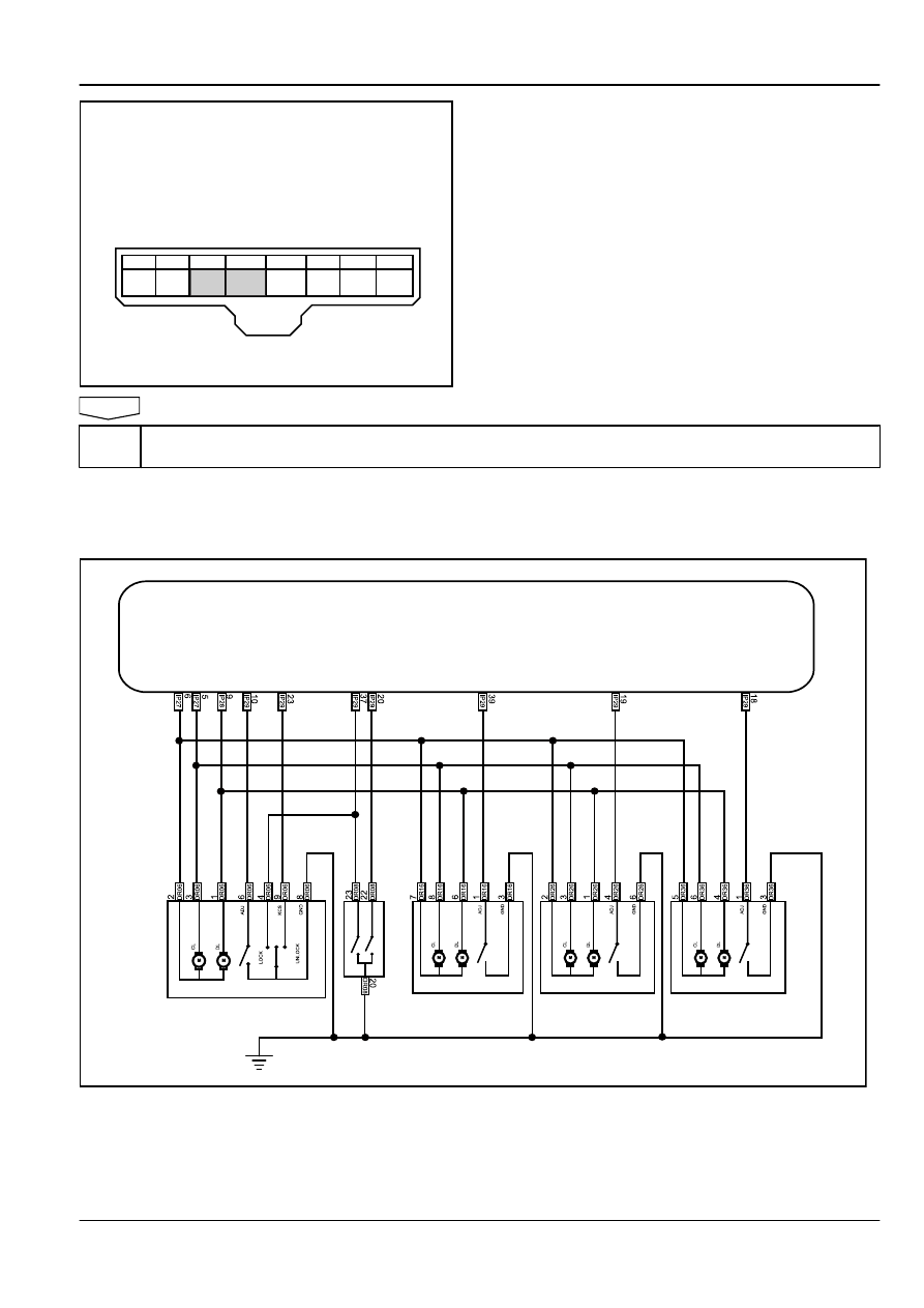
Schematic:

Body Control Module

Left Front Door Lock Assembly

Right Front Door Lock 

Assembly

Left Rear Door Lock 

Assembly

Right Rear Door Lock 

Assembly

Left 

Front 

Door 

switch

FE11-5801b

Body Electric

Central Locking

11-345

Diagnostic Steps:

Step 1

Use the remote key to perform the super locking.

Is the remote control super locking working?

Yes

Go to step 3

No

Step 2

Check for remote anti-theft system potential malfunction.

(a)

Check and repair the remote anti-theft system potential
malfunction.

Is the super-locking working?

Yes

System normal

No

Step 3

Use a mechanical keys to lock and unlock.

Is the mechanical key working?

Yes

Go to step 5

No

Step 4

Repair the locking and unlocking malfunction.

(a)

Repair the locking and unlocking malfunction. Refer to

11.9.7.4


Mechanical Key / Central Locking Switch Can Not

Lock All Doors

,

11.9.7.5


Mechanical key / Central Locking

Switch Can Not Unlock All Doors

.

Confirm the lock and unlocking are working properly.

Confirm the Super Lock function is normal.

Yes

System normal

No

Step 5

Measure the BCM harness connector IP28 terminal No.9 voltage.

11-346

Central Locking

Body Electric

1

9

2

10

11

12

13

14

15

16

17

3

4

5

6

7

8

Body Control Module 2 Harness Connector IP28

FE11-5814b

(a)

Perform the super locking, while measure the BCM harness
connector IP28 terminal No.9 voltage with a multimeter.
Standard Voltage: 11-14 V

Is the voltage specified value?

Yes

Go to step 7

No

Step 6

Replace the BCM.

(a)

Replace the BCM. Refer to 

11.10.8.1


BCM Replacement

.

Confirm the Super Locking function is normal.

Yes

System normal

No

Step 7

Check the circuit between the BCM harness connector IP28 and the electric door lock assembly harness
connector.

(a)

Disconnect the BCM harness connector IP28 and the electric
door lock assembly harness connector.

(b)

Measure resistance between the BCM harness connector
IP28 and the electric door lock assembly super-locking
harness connector with a multimeter
Standard Resistance: Less than 1 Ω

Is the resistance specified value?

Yes

Go to step 9

No

Step 8

Check  the  open  circuit  between  the  BCM  harness  connector  IP28  and  the  electric  door  lock  harness
connector.

(a)

Repair the circuit between the BCM harness connector IP28
and the electric door lock assembly super-locking harness
connector.

Confirm Super Locking function is normal.

Yes

System normal

Body Electric

Central Locking

11-347

No

Step 9

Replace the lock motor.

(a)

Replace the lock motor.

Confirm the repair is completed.

Next

Step 10

System normal.

11.9.7.7 Rear Compartment Lid Can Not Be Opened (Sedan)

Schematic:

2

SO54

1

SO54

M

Rear Compartment Lid Release Switch

Rear Compartment Lid Release Motor

Body 

Control 

Module

FE11-5815b

Diagnostic Steps:

Note

When there is not a remote control key, use the scan tool special setting function to drive the door locks. Select as the
following sequence: body control module / BCM special set features / rear compartment Lid (rear compartment) open
control.

Step 1

Use the remote key to open the rear compartment lid.

Is the remote key working?

11-348

Central Locking

Body Electric


содержание   ..   454  455  456  457  458  459 ..