содержание .. 271 272 273 274 275 ..
Geely EC718, EC718RV, EC715, EC715RV. Manual part - 274
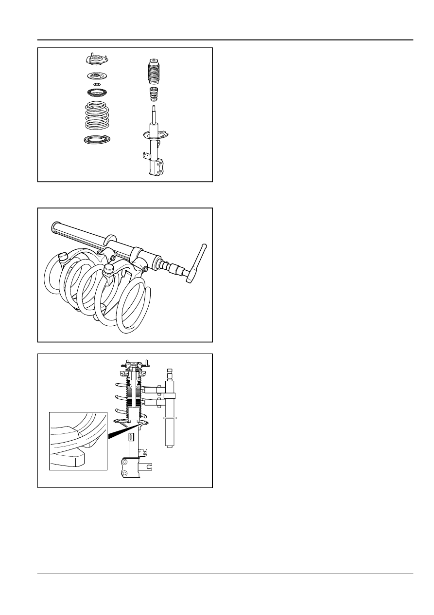
FE04-0021b
4.
Remove the front shock absorber upper mount,front coil
spring upper mount, the front coil spring upper vibration
insulator pad, the front suspension coil spring, the front
shock absorber dust cover, the front shock absorber
buffer block and the front coil spring lower vibration
insulator pad.
Installation Procedure:
FE04-0022b
1.
Use the spring compression tool to compress the coil
spring.
FE04-0023b
2.
On the front shock absorber bracket, install the front coil
spring lower vibration insulation pad, front shock absorber
buffer block, the front shock absorber dust cover, the front
suspension coil spring, the front coil spring upper vibration
insulation pad, the front coil spring upper mount and the
front shock absorber assembly.
Note
Install the coil spring bottom to the shock absorber
spring mount notch.
Suspension System
Front Suspension
4-25