Geely EC718, EC718RV, EC715, EC715RV. Manual part - 243


  Главная      Geely     Geely Emgrand EC718, EC718RV, EC715, EC715RV. Workshop Manual year 2009


поиск по сайту            


содержание   ..   240  241  242  243  244  ..


Geely EC718, EC718RV, EC715, EC715RV. Manual part - 243


3.2.6 Removal and Installation
3.2.6.1 Clutch Pedal Replacement

Removal Procedure:

Warning!

Refer to "Battery Disconnection Warning" in "Warnings
and Notices".

FE03-0201b

1.

Disconnect  the  battery  negative  cable.  Refer  to

2.11.8.1


Battery Disconnection

.

2.

Remove 

the 

instrument 

panel. 

Refer 

to

12.8.3.1


Instrument Panel Replacement

.

Note

Please use trim repair tools, otherwise interior trims
will easily be scratched.

3.

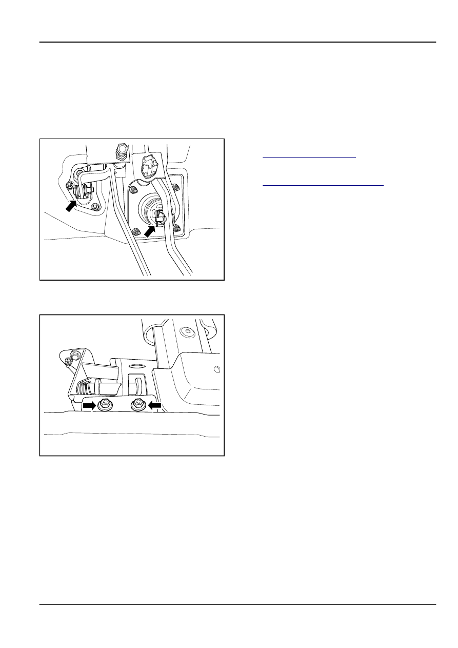
Disconnect brake switch wiring harness connector.

4.

Separate the clutch master cylinder piston rod U-shaped
clip and the clutch pedal.

5.

Separate  the  vacuum  brake  booster  rod  U-shaped  clip
and brake pedal.

FE03-0225b

6.

Remove the clutch pedal assembly upper retaining bolts.

Transmission / Drive Axle

Clutch System

3-15

FE03-0202b

7.

Remove clutch / brake pedal assembly bolt and nuts.

FE03-0203b

8.

Remove  the  clutch  /  brake  pedal  assembly,  remove
screws and pull retaining nuts out of the pedal.

9.

Remove the return spring and clutch pedal.

Installation Procedure:

FE03-0204b

1.

Install the return spring and clutch pedal.

2.

Install the pedal screws and nuts.

Torque: 35 Nm (Metric) 25.9 lb-ft (US English)

Note

Apply  grease  on  the  pedal  axle  and  the  return
spring.

3-16

Clutch System

Transmission / Drive Axle

FE03-0205b

3.

Install clutch / brake pedal assembly bolt and nuts.

Torque: 23 Nm (Metric) 17.0 lb-ft (US English)

FE03-0226b

4.

Install clutch pedal assembly upper retaining bolts.

Torque: 23 Nm (Metric) 17.0 lb-ft (US English)

FE03-0201b

5.

Install the vacuum brake booster rod U-shaped clip and
the brake pedal connecting pin.

6.

Install the clutch master cylinder piston rod U-shaped clip
and the clutch pedal connecting pin.

7.

Connect brake switch harness connector.

8.

If necessary, adjust the clutch pedal free travel.

9.

Install the instrument panel.

10. Connect the battery negative cable.

3.2.6.2 Clutch Master Cylinder Replacement

Removal Procedure:

Warning!

Refer to "Battery Disconnection Warning" in "Warnings
and Notices".

Transmission / Drive Axle

Clutch System

3-17

1

2

FE03-0206b

1.

Disconnect  the  battery  negative  cable.  Refer  to

2.11.8.1


Battery Disconnection

.

2.

Remove  Instrument  panel  lower  left  panel.  Refer  to

12.8.3.1


Instrument Panel Replacement

.

Note

Before  disconnecting  the  cylinder,  release  the
clutch / brake fluid.

3.

Loose thread on the master cylinder drive dual wire hoop,
Remove tank to the master cylinder oil inlet hose (1).

4.

Disconnect clutch master cylinder metal connector (2).

3

2

3

1

FE03-0207b

5.

Remove pin (1) from the clutch pedal and the piston rod
U-shaped clip, and pull out connecting pin (1).

6.

Release  the  clutch  master  cylinder  piston  rod  and  the
piston rod between the U-shaped clip locking nut, piston
rod U-shaped clip from the clutch master cylinder piston
rod on the screw of 2.

7.

Remove the clutch master cylinder retaining nuts (3).

FE03-0208b

8.

Pull out of master cylinder along the direction of the engine
compartment.

3-18

Clutch System

Transmission / Drive Axle


содержание   ..   240  241  242  243  244  ..