содержание .. 189 190 191 ..
Geely EC718, EC718RV, EC715, EC715RV. Manual part - 190
FE02-5350b
1
17
33
53
54
55
56
57
58
59
60
61
62
63
64
65
66
67
68
69
70
71
72
73
34
35
36
37
38
39
40
41
42
43
44
45
46
47
48
49
50
51
52
18
19
20
21
22
23
24
25
26
27
28
29
30
31
32
2
3
4
5
6
7
8
9
10
11
12
13
14
15
16
A
B
C
D
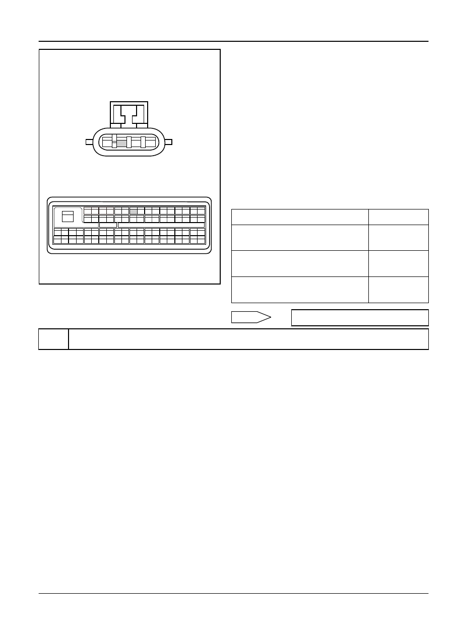
Pre-catalytic Oxygen Sensor Harness
Connector EO02
ECM Harness Connector EO01
(a)
Turn the ignition switch to "OFF" position.
(b)
Disconnect oxygen sensor wiring harness connector EO02.
(c)
Disconnect ECM harness connector EO01.
(d)
Measure resistance between pre-catalytic oxygen sensor
wiring harness connector EO02 terminal B and ECM harness
connector terminal No.10. Check whether the circuit is open.
otherwise, repair the faulty part.
(e)
Measure resistance between pre-catalytic oxygen sensor
wiring harness connector EO02 terminal B and a reliable
ground. Check whether the circuit is short to ground.
otherwise, repair the faulty part.
(f)
Measure voltage between pre-catalytic oxygen sensor wiring
harness connector EO02 terminal B and a reliable ground.
Check whether the circuit is short to power supply. Otherwise,
repair the faulty part.
Test Items
Standard Value
Resistance Between EO02 (B) and EO01
(10)
Less than 1 Ω
Resistance Between EO02 (B) and A
Reliable Ground
10 kΩ or higher
Voltage Between EO02 (B) and A Reliable
Ground
0 V
Normal
Step 12
Check pre-catalytic oxygen sensor ground circuit..
Engine
Control System JL4G15-D
2-675