содержание .. 182 183 184 185 186 ..
Geely EC718, EC718RV, EC715, EC715RV. Manual part - 185
Yes
Step 5
Replace intake manifold absolute pressure sensor.
Next
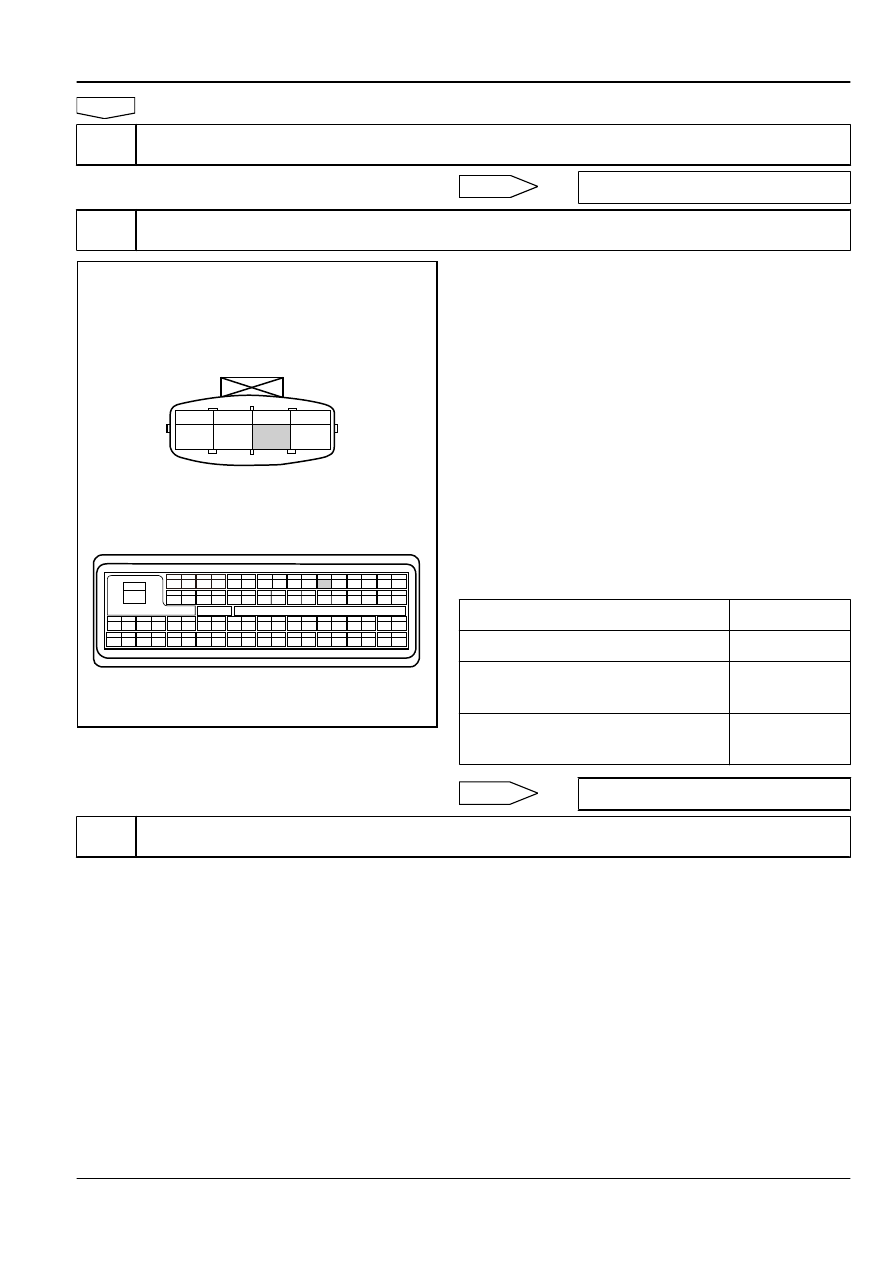
Step 6
Check sensor 5 V reference voltage circuit.
FE02-5338b
1
17
33
53
54
55
56
57
58
59
60
61
62
63
64
65
66
67
68
69
70
71
72
73
34
35
36
37
38
39
40
41
42
43
44
45
46
47
48
49
50
51
52
18
19
20
21
22
23
24
25
26
27
28
29
30
31
32
2
3
4
5
6
7
8
9
10
11
12
13
14
15
16
1 2 3 4
Intake Air Temperature/Pressure Sensor Harness
Connector EO16
ECM Harness Connector EO01
(a)
Turn the ignition switch to "OFF" position.
(b)
Disconnect intake manifold absolute pressure sensor wiring
harness connector EO16.
(c)
Disconnect ECM harness connector EO01.
(d)
Measure resistance between intake manifold absolute
pressure sensor wiring harness connector EO16 terminal No.
3 and ECM harness connector terminal No.6. Check whether
the circuit is open. Otherwise, repair the fault part.
(e)
Measure resistance between intake manifold absolute
pressure sensor wiring harness connector EO16 terminal No.
3 and a reliable ground. check whether the circuit is short to
ground. Otherwise, repair the fault part.
(f)
Measure resistance between intake manifold absolute
pressure sensor wiring harness connector EO16 terminal No.
3 and power supply. check whether the circuit is short to
power supply. Otherwise, repair the fault part.
Test Items
Standard Value
Resistance Between EO16 (3) and EO01 (6)
Less than 1 Ω
Resistance Between EO16 (3) and A
Reliable Ground
10 kΩ or higher
Voltage Between EO16 (3) and A Reliable
Ground
0 V
Next
Step 7
Check sensor signal circuit.
Engine
Control System JL4G15-D
2-655