содержание .. 150 151 152 153 ..
Geely EC718, EC718RV, EC715, EC715RV. Manual part - 152
01
MAIN
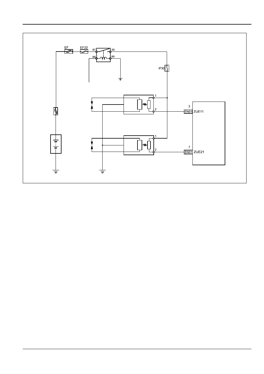
IG1 Relay
To Ignition Switch
Battery
1,4 Cylinder Ignition Coil
2,3 Cylinder Ignition Coil
Engine
Control
Module
FE02-9000b
Engine
Ignition System JL4G18-D
2-523