Geely EC718, EC718RV, EC715, EC715RV. Manual part - 56


  Главная      Geely     Geely Emgrand EC718, EC718RV, EC715, EC715RV. Workshop Manual year 2009


поиск по сайту            


содержание   ..  50  51  52  53  54  55  56  57  ..


Geely EC718, EC718RV, EC715, EC715RV. Manual part - 56


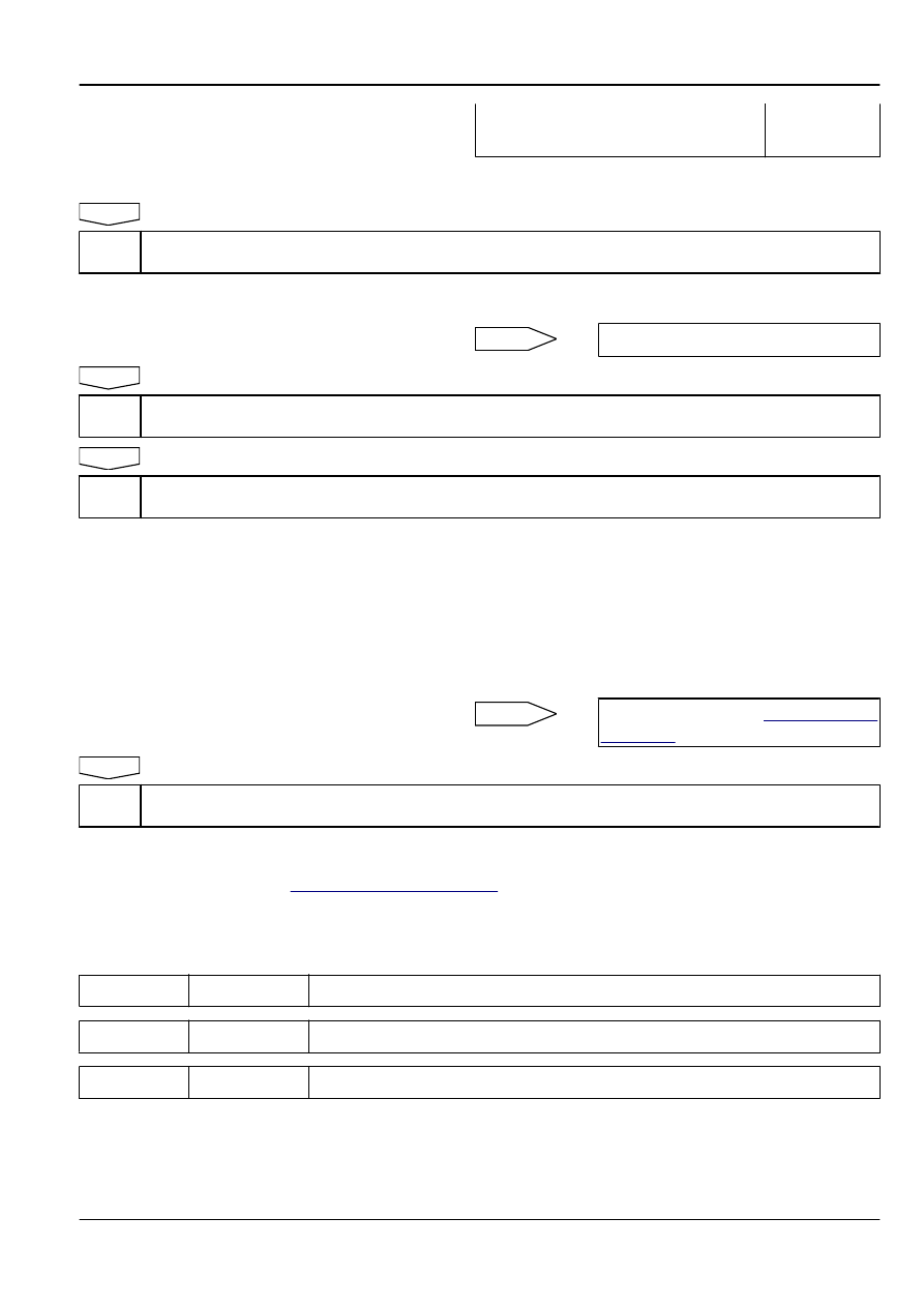
Voltage Between EN13 (1) and a Reliable
Ground

0 V

Execute next step as per normal.

Next

Step 7

Check ECM power supply circuit.

(a)

Check whether ECM power supply circuit is normal.

(b)

Check whether ECM ground circuit is normal.

No

Repair the faulty part.

Yes

Step 8

Replace ECM.

Next

Step 9

Use scan tool to confirm whether the DTC code is stored again.

(a)

Connect scan tool to the datalink connector.

(b)

Turn the ignition switch to "ON" position.

(c)

Clear DTC code.

(d)

Start and run the engine at idle speed to warm up the engine
for at least 5 min.

(e)

Road test the vehicle for at least 10 min.

(f)

Read control system DTC code again to confirm that the
system has no DTC code.

No

Intermittent Fault. Refer to 

2.2.7.3


Intermittent

Fault Check

Yes

Step 10

Diagnostic completed.

5. Repair Instructions:

Replace the fuel injector. Refer to 

2.2.8.2


Fuel Injector Replacement

.

2.2.7.27 DTC P0204 P0270 P0271

1. DTC Descriptor:

DTC

P0204

Cylinder No.4 Fuel Injection Control Circuit Open

DTC

P0270

Cylinder No.4 Fuel Injector Control Circuit Short to Ground

DTC

P0271

Cylinder No.4 Fuel Injector Control Circuit Short to Power Supply

Engine

Control System JL4G18-D

2-139

Fuel injector operating voltage is provided by The Main Relay which is controlled by ECM. Battery voltage passes through the main
relay terminal No.3 to all fuel injector wiring harness connectors terminal No.1. ECM controls fuel injector ground circuit by ECM
harness  connector  EN01  terminal  No.64.  ECM  monitors  all  fuel  injector  driver  circuit  status,  if  ECM  detects  driving  circuit
corresponding voltage is incorrect, ECM will set up a fuel injector control circuit fault DTC code.

2. Conditions For Setting DTC and The Fault Location:

DTC Code

DTC Detection Strategy

Conditions For Setting The

DTC (Control Strategy)

Fault Locations

P0204
P0270
P0271

Hardware Circuit Checks

1. Circuit Open.

2. Circuit Short to Ground.

3. Circuit Short to Power Supply.

1. Sensor Circuit

2. Sensor

3. ECM

3. Schematic:

12

From Battery

Main Relay

Engine 

Control 

Module

Cylinder No.4 Fuel Injector

FE02-5069b

4. Diagnostic Steps:

Note

Before carrying out this diagnosis step, observe the data list on scan tool and analyze the accuracy of the data, as
these will help with quick diagnosis.

Step 1

Initial Inspection

2-140

Control System JL4G18-D

Engine

(a)

Check the fuel injector wiring harness connector for damage,
poor connection, aging or signs of loosening.

Next

Step 2

Measure the resistance of fuel injector assembly.

2

1

Cylinder No.4 Fuel Injector

FE02-5070b

(a)

Disconnect the fuel injector wiring harness connector EN14.

(b)

Measure resistance between the two fuel injector terminals.

Standard Resistance: 20°C (68 ºF) 11.5-12.5 Ω

(c)

Connect the fuel injector wiring harness connector EN14.

No

Replace fuel injector assembly. Refer to

2.2.8.2


Fuel Injector Replacement

Yes

Step 3

Measure fuel injectors working power supply.

1

2

Cylinder No.4 Fuel Injector Harness 

Connector EN14

FE02-5071b

(a)

Turn the ignition switch to "OFF" position.

(b)

Disconnect cylinder No.4 fuel injector wiring harness
connector EN14.

(c)

Turn the ignition switch to "ON" position.

(d)

Measure voltage between cylinder No.4 fuel injector wiring
harness connector EN14 No.1 terminal and a reliable ground.

Standard Voltage: 11-14 V

(e)

Connect cylinder No.4 fuel injector wiring harness connector
EN14.

Is voltage normal?

No

Go to step 5

Yes

Step 4

Check the fuel injector control circuit.

Engine

Control System JL4G18-D

2-141

1

2

Cylinder No.4 Fuel Injector Harness 

Connector EN14

FE02-5072b

(a)

Turn the ignition switch to "OFF" position.

(b)

Disconnect cylinder No.1 fuel injector wiring harness
connector EN14.

(c)

Connect test lamp made from light-emitting diodes to the fuel
injector wiring harness connector EN14 terminal No.1 and
No.2.

(d)

Start the engine.

(e)

Check whether the test lamp is flashing as per normal.

Is test lamp flashing as per normal?

No

Go to step 6

Yes

Go to step 7

Step 5

Check and repair cylinder No.4 fuel injector power supply circuit.

G

1

2

5 3

1413 12 1110

5

1

2

3

4

6

7

8

9

J

L

K

I

G

D

C

B

E

F

A

86

86

30

87

85

86

86

87

87

87

30

30

30

85

85

85

2

2

3

3

5

5

1

1

1

2

5 3

1

2

5 3

86

87

30

1

1

2

5
3

2

5
3

85

EF01

EF21

EF18

EF25

EF20

EF29

EF06

EF02

EF30

EF17

EF19

EF23

EF22

EF26

EF24

EF08

EF27

EF28

EF05

EF07

EF16

EF04

EF03

EF15

EF12

EF10

EF1

1

EF09

EF13

EF14

EF32

EF31

1

2

Cylinder No.4 Fuel Injector Harness 

Connector EN14

FE02-5073b

(a)

Turn the ignition switch to "OFF" position.

(b)

Disconnect the fuel injector wiring harness connector EN14.

(c)

Remove the engine main relay.

(d)

Measure resistance between cylinder No.4 fuel injector
wiring harness connector EN14 terminal No.1 and engine
main relay terminal No.3.

(e)

Measure resistance between cylinder No.4 fuel injector
wiring harness connector EN14 terminal No.1 and a reliable
ground

Test Items

Standard Value

EN14 (1) and Main Relay Terminal No.3

Less than 1 Ω

EN14 (1) and a Reliable Ground

10 kΩ or higher

(f)

Install the engine main relay.

(g)

Connect cylinder No.4 fuel injector wiring harness connector
EN14.

Exclude the fuel injector power supply circuit fault.

Next

Go to step 9

Step 6

Check cylinder No.4 fuel injector control circuit.

2-142

Control System JL4G18-D

Engine


содержание   ..  50  51  52  53  54  55  56  57  ..