Geely EC718, EC718RV, EC715, EC715RV. Manual part - 44


  Главная      Geely     Geely Emgrand EC718, EC718RV, EC715, EC715RV. Workshop Manual year 2009


поиск по сайту            


содержание   ..  40  41  42  43  44  45 ..


Geely EC718, EC718RV, EC715, EC715RV. Manual part - 44
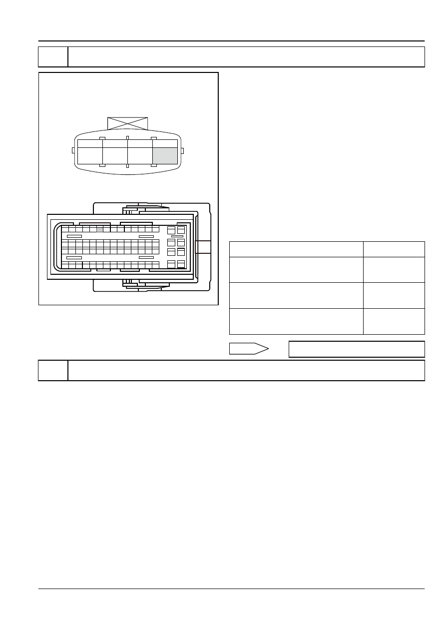


Step 7

Check sensor signal circuit.

1

3

5

7

8

6

4

2

9

10

11

12

13

23

24

25

26

27

28

29

30

37

51

52

53

54

55

56

57

58

59

60

61

62

63

64

38

39

40

41

42

43

44

45

46

47

48

49

50

31

32

33

34

35

36

14

15

16

17

18

19

20

21

22

ECM Harness Connector EN01

1

2

3

4

Intake Air Pressure Temperature 

Sensor Harness Connector EN16

FE02-5021b

(a)

Turn the ignition switch to "OFF" position.

(b)

Disconnect intake manifold absolute pressure sensor wiring
harness connector EN16.

(c)

Disconnect ECM harness connector EN01.

(d)

Measure resistance between intake manifold absolute
pressure sensor harness connector EN16 terminal No.4 and
ECM harness connector terminal No.59. Check whether the
circuit is open. If there is no open circuit, repair faulty part.

(e)

Measure resistance between intake manifold absolute
pressure sensor harness connector EN16 terminal No.4 and
a reliable ground. Check whether the circuit is short to
ground. If there is no short circuit, repair faulty part.

(f)

Measure voltage between intake manifold absolute pressure
sensor harness connector EN16 terminal No.4 and a reliable
ground. Check whether the circuit is short to power supply. If
there is no short circuit, repair faulty part.

Test Items

Standard Value

Resistance Between EN16 (4) and EN01
(59)

Less than 1 Ω

Resistance Between EN16 (4) and A
Reliable Ground

10 kΩ or higher

Voltage Between EN16 (4) and A Reliable
Ground

0 V

Normal

Go to step 9

Step 8

Check sensor ground circuit.

Engine

Control System JL4G18-D

2-91

1

3

5

7

8

6

4

2

9

10

11

12

13

23

24

25

26

27

28

29

30

37

51

52

53

54

55

56

57

58

59

60

61

62

63

64

38

39

40

41

42

43

44

45

46

47

48

49

50

31

32

33

34

35

36

14

15

16

17

18

19

20

21

22

ECM Harness Connector EN01

1

2

3

4

Intake Air Pressure Temperature 

Sensor Harness Connector EN16

FE02-5022b

(a)

Turn the ignition switch to "OFF" position.

(b)

Disconnect intake manifold absolute pressure sensor wiring
harness connector EN16.

(c)

Disconnect ECM harness connector EN01.

(d)

Measure resistance between intake manifold absolute
pressure sensor harness connector EN16 terminal No.1 and
ECM harness connector terminal No.40. Check whether the
circuit is open. If there is no open circuit, repair the faulty part.

(e)

Measure voltage between intake manifold absolute pressure
sensor harness connector EN16 terminal No.1 and a reliable
ground. Check whether the circuit is short to power supply. If
there is no short circuit, repair the faulty part.

Test Items

Standard Value

Resistance Between EN16 (1) and EN01
(40)

Less than 1 Ω

Voltage Between EN16 (1) and A Reliable
Ground

0 V

Execute next step as per normal.

Next

Step 9

Check ECM power supply circuit.

(a)

Check whether ECM power supply circuit is normal.

(b)

Check whether ECM ground circuit is normal.

No

Repair the faulty part.

Yes

Step 10

Replace ECM.

Next

Step 11

Use scan tool to confirm whether the DTC code is stored again.

(a)

Connect scan tool to the datalink connector.

(b)

Turn the ignition switch to "ON" position.

(c)

Clear DTC code.

(d)

Start and run the engine at idle speed to warm up the engine
for at least 5 min.

(e)

Read control system DTC code again to confirm that the
system has no DTC code.

No

Intermittent Fault. Refer to 

2.2.7.3


Intermittent

Fault Check

2-92

Control System JL4G18-D

Engine

Yes

Step 12

Diagnostic completed.

5. Repair Instructions:

Replace the MAP sensor. Refer to 

2.2.8.7


Intake Air Pressure and Temperature Sensor Replacement

.

Refer to 

2.2.8.8


Engine Control Module Replacement

Replace ECM.

2.2.7.18 DTC P0112 P0113

1. DTC Descriptor:

DTC

P0112

Intake Air Temperature Sensor Signal Voltage Too Low

DTC

P0113

Intake Air Temperature Sensor Signal Voltage Too High

The sensor is an integrated part of the engine intake pressure sensor for Measure the temperature of air entering the engine. ECM
provides 5 V reference voltage through ECM harness connector EN01 terminal No.25 to the intake air pressure and temperature
sensor wiring harness connector EN16 terminal No.2. At the same time it provides ECM internal low reference voltage through EN01
terminal No.40 to intake air pressure and temperature sensor EN16 terminal No.1. When the intake air pressure and temperature
sensors is cold, the thermistor value used to measure temperature is high. When the air temperature rises, the resistance decreases.
When the resistance is higher, ECM will detect the signal circuit with a higher voltage. With the decrease of resistance, ECM detected
intake air temperature signal circuit voltage also decreases.

2. Conditions For Setting DTC and The Fault Location:

DTC Code

DTC Detection

Strategy

Conditions For Setting The DTC (Control Strategy)

Fault Locations

P0112
P0113

1. More Than the Upper

Limit

2. Less than the Lower

Limit

1. Short to ground. Intake air temperature is higher than

138°C (280.4 ºF).

2. Short to power supply. Intake air temperature is less than

-38.3°C (-36.9 ºF).

3. Startup time more than 240 s.

4. Engine idle.

1. Sensor Circuit

2. Sensor

3. ECM

3. Schematic:

Refer to 

2.2.7.17


DTC P0105 P0106 P0107 P0108

in schematics.

4. Diagnostic Steps:

Note

Before carrying out this diagnosis step, observe the data list on scan tool and analyze the accuracy of the data, as
these will help with quick diagnosis.

Step 1

Initial Inspection

Check the existence of the following conditions:

(a)

Sensor Housing Damage

(b)

Sensor Loose or Not Properly Installed

Engine

Control System JL4G18-D

2-93

(c)

Sensor Wiring Harness Connector Loose

Next

Note

It is not allowed to connect intake manifold absolute pressure sensor 5 V reference voltage circuit and other components
of the vehicle, as this will damage the sensors and ECM.

Step 2

Measure intake air temperature sensor resistance.

Intake Air Temperature/Pressure Sensor

FE02-5024b

(a)

Turn the ignition switch to "OFF" position.

(b)

Disconnect intake air pressure and temperature sensor
wiring harness connector EN16.

(c)

Measure intake air temperature sensor resistance.

Standard Resistance (Refer to the specific
parameters

2.2.1.2


Temperature Sensor Temperature and

Resistance Correlation

): 20°C (68 ºF) 2,400 Ω

(d)

Connect intake air pressure and temperature sensor wiring
harness connector EN16.

Is resistance the specified value?

No

Replace intake air pressure and temperature
sensor. Go to step 9

Yes

Step 3

Measure intake air temperature sensor signal.

1

2

3

4

Intake Air Pressure Temperature 
Harness Connector EN16

FE02-5025b

(a)

Turn the ignition switch to "OFF" position.

(b)

Disconnect intake air pressure and temperature sensor
wiring harness connector EN16.

(c)

Turn the ignition switch to "ON" position.

(d)

Measure voltage between intake air pressure and
temperature sensor wiring harness connector EN16 terminal
No.2 and a reliable ground.

Standard Voltage: 4.7-5.5 V

(e)

Connect intake air pressure and temperature sensors
connector EN16.

Is voltage normal?

No

Go to step 5

Yes

Step 4

Measure intake air temperature sensor to ground circuit.

2-94

Control System JL4G18-D

Engine


содержание   ..  40  41  42  43  44  45 ..