Freightliner FLA/FLB/FLC/FLD/FLL. Manual - part 4
The M4 Maintenance Interval Operations table lists
all maintenance operations that are to be performed
at the M4 maintenance interval. Maintenance opera-
tion numbers are reference numbers used to help
you find detailed instructions in this manual on the
maintenance operations to be performed. Perform all
maintenance interval operations in M1, M2, and M3
when performing M4 maintenance interval opera-
tions.
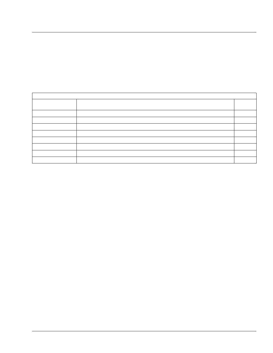
M4 Maintenance Interval Operations for Service Schedules I, II, and III
M4 Maintenance Interval Operations for Service Schedules I, II, and III
Maintenance
Operation Number
Operation Description
Check
Perform all M1 Operations
Perform all M2 Operations
Perform all M3 Operations
Radiator Pressure Flushing and Coolant Changing
Allison Transmission Fluid and Filter Changing
Bendix Air Dryer Desiccant Replacing (AD–2)
Bendix Air Dryer Desiccant Replacing (AD–4 or AD–9)
Meritor WABCO System Saver 1000 Air Dryer Desiccant Replacing
General Information
00
M4 Maintenance Interval Operations Table: 00-10
00/17