Freightliner Business Class. Manual - part 27


  Index      Freightliner     Freightliner Business Class Trucks - service manual


Search            


Content   ..  25  26  27  28   ..


Freightliner Business Class. Manual - part 27


1

2

3

4

5

6

7

8

9

10

1

2

3

4

5

6

1

2

3

4

5

f400057

05/27/93

1

2

3

4

5

6

7

8

A

B

C

D

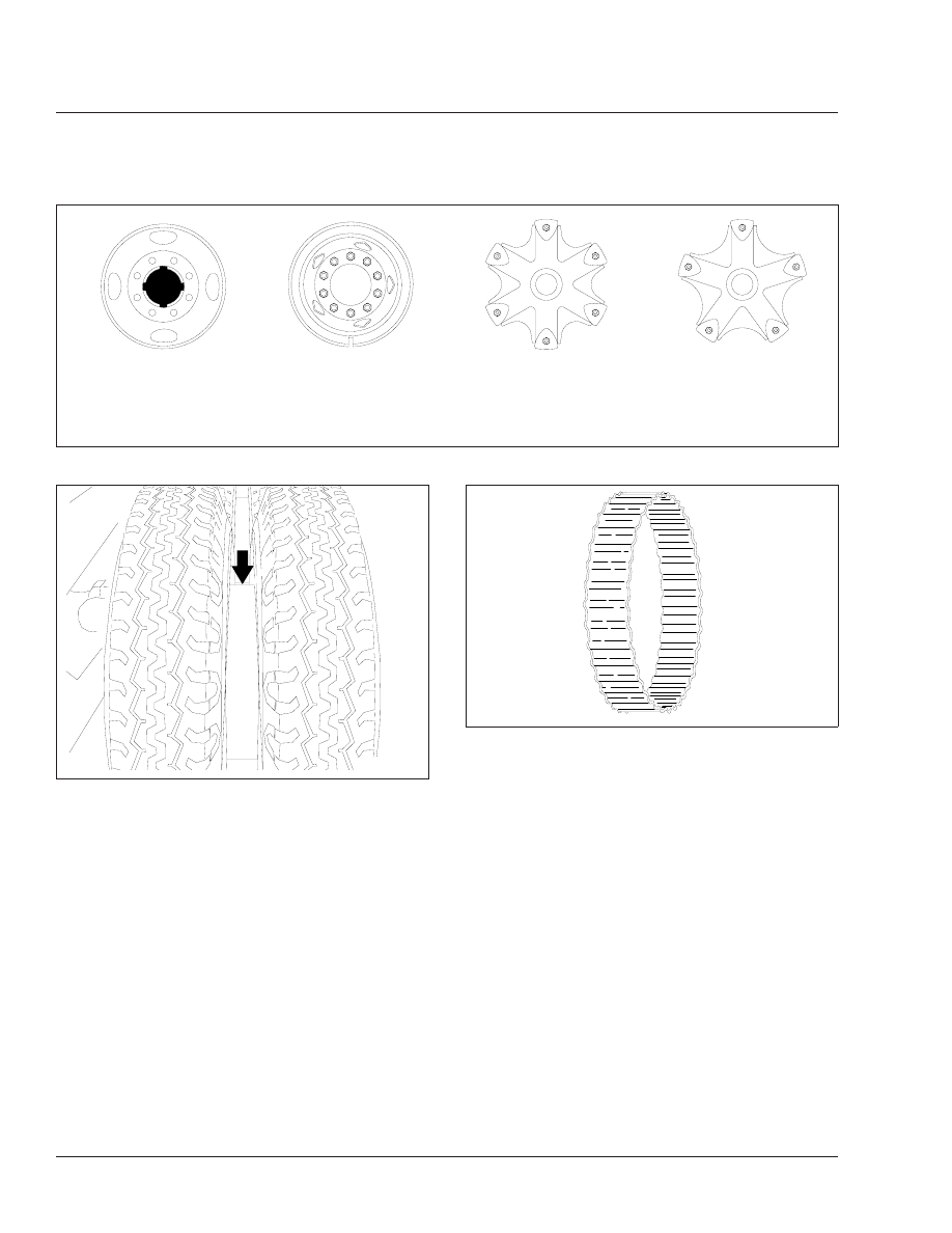
A. 8-Stud Disc Wheel
B. 10-Stud Disc Wheel

C. 6-Spoke Wheel
D. 5-Spoke Wheel

Fig. 1, Wheel Nut and Rim Nut Tightening Sequence

f400033a

05/16/94

Fig. 2, Non-Corrugated Channel Spacer

f400032a

10/05/94

Fig. 3, Corrugated Channel Spacer

Wheels and Tires

40

Business Class Trucks Maintenance Manual, January 1998

40/2

Title of Maintenance Operation (MOP)

MOP Number

Driveline Inspecting . . . . . . . . . . . . . . . . . . . . . . . . . . . . . . . . . . . . . . . . . . . . . . . . . . . . . . . . . . . . . . . . 41–01

Driveline Lubricating. . . . . . . . . . . . . . . . . . . . . . . . . . . . . . . . . . . . . . . . . . . . . . . . . . . . . . . . . . . . . . . . 41–02

Driveline

41

Index, Alphabetical

Business Class Trucks Maintenance Manual, January 1998

41–01 Driveline Inspecting

Inspecting

1.

Check that the yoke-strap capscrews (

Fig. 1

,

Ref. 4) are tightened as follows:

Spicer 1590 and 1610: 50 to 60 lbf·ft (68
to 81 N·m)

Spicer 1710: 125 to 135 lbf·ft (170 to 183
N·m)

CAUTION

Do not overtighten the yoke-strap capscrews, due
to the extreme load occurring at high-speed rota-
tion. A loose or broken capscrew at any point in
the driveline weakens the driveline connection,
which could eventually result in serious vehicle
damage.

2.

Check each of the output and input end yokes
(

Fig. 1

Refs. 2 and 11) for cracks and loose-

ness. Replace cracked yokes. If any end yoke
can be moved in or out on its shaft, or can be
rocked on its shaft, disconnect the driveshaft and
U-joint from the end yoke. Check the drive com-
ponent’s shaft seal for leakage or other visible
damage that may have been caused by the
loose yoke. Replace the seal if needed. Tighten
the end-yoke nut to the value in

Table 1

If the

end yoke is still loose after tightening the yoke
nut, install a new yoke and yoke nut.

End-Yoke Nut Torque Specifications

Description

Thread

Size

Torque

lbf·ft

(N·m)

Transmissions

Fuller FS 4005,
5005, 5106,
6105, and 6206

1-1/4–18

300–350

(405–475)

Fuller RT 6609,
RT/RTO 6610, and
RT 8609

1-1/2–18

400–450

(540–610)

Fuller T 8607,
RT 7608LL,
RT 8608L, and
RT/RTO 6613

2–16

450–500

(610–675)

End-Yoke Nut Torque Specifications

Description

Thread

Size

Torque

lbf·ft

(N·m)

Allison AT-545

1/2–20

*

100–120

(140–160)

Allison MD Series

2–16

600–800

(815–1085)

Single Axle Input Shaft

Meritor RS–13–120,
RS–15–120 and –210,
RS–17–140 and –20,
RS–19–145 and –220,
and
RS–21–145 and –230

M32 x 1.5

740–920

(1000–1250)

Meritor RS–23–160

M45 x 1.5

1000–1230

(1355–1670)

Meritor RS–23–240

M39 x 1.5

920–1130

(1250–1530)

Tandem Axle Input and Output Shafts

Meritor
RD– and RR–17–145,
(of RT–34–145), and
RD– and RR–20–145
(of RT–40–145)

M39 x 1.5

920–1130

(1250–1530)

Coupling Shaft (Midship Bearings)

Spicer 1590, 1610,

and 1710

1-1/4–18

475–525

(644–712)

*

The Allison AT-545 transmission output shaft end-yoke is retained by a

1/2-20 x 1-1/2-inch bolt and a 1-1/16-inch washer. Both the bolt and the
washer must be replaced each time they are removed.

Table 1, End-Yoke Nut Torque Specifications

NOTE: If the end-yoke locknut was removed for
any reason, install a new one.

3.

Check the U-joint assemblies for wear by at-
tempting to move the driveshaft up and down,
and from side to side. If movement of the U-joint
trunnion in the bearings is greater than 0.006
inch (0.15 mm), replace the U-joint assembly.

4.

Check the midship bearing and bracket for loose-
ness and deterioration by attempting to move the
driveshaft up and down, and from side to side. If
the bearing is loose on its shaft, or rattles, re-
place it. If the bearing bracket is loose on the
frame, or the bearing mount is loose on the
bracket, tighten the mounting bolt nuts 91 lbf·ft

Driveline

41

Business Class Trucks Maintenance Manual, January 1998

41/1

(123 N·m). Replace the midship bearing assem-
bly if the rubber cushion is worn or oil-soaked.

5.

Check the slip-joints for spline wear by trying to
bend the sleeve-yoke and splined shaft back and
forth (

Fig. 2

). If looseness is greater than 0.007

inch (0.18 mm), replace both the sleeve-yoke
and the splined shaft.

6.

Check the driveshaft tubes for dents, bends,
twists, or other damage. If any tube appears to
be damaged, remove the driveshaft and check
the runout on the tube. If the tube is not straight
(and cannot be straightened) within 0.015 inch
(0.38 mm) on the slip-joint seal surface of the

splined shaft, 0.020 inch (0.51 mm) on the tube
3 inches (76 mm) from the front and rear welds,
and 0.025 inch (0.635 mm) at the center of the
tube, replace the tube. See

Fig. 3

.

If the driveshaft tube requires straightening or
replacement, balance the repaired driveshaft be-
fore installing it. See Group 41 of the

Business

Class

®

Trucks Service Manual

.

7.

Check the driveshaft for missing balance
weights, and for debris build-up. Remove any
build-up. If any balance weights are missing, re-

f410057a

10/06/94

1

2

3

5

6

4

2

4

7

16

15

14

13

18

17

9

8

3

7

10

11

12

NOTE: Not all fasteners are shown.

1.

Transmission

2.

Half-Round End Yoke

3.

U-Joint Assembly

4.

Yoke Strap and Capscrew

5.

Coupling Shaft

6.

Midship Bearing and Mount

7.

Bearing Cup

8.

Slip-Joint Assembly

9.

Driveshaft Tube

10. Driveshaft Yoke
11. Input Shaft Half-Round End

Yoke

12. Rear Axle

13. Splined Shaft
14. Dust Seal
15. Sleeve Yoke
16. Full-Round-Yoke Lug
17. U-Joint Cross
18. Lockplate and Capscrew

Fig. 1, Driveline Assembly With Midship Bearing For Single-Axle Installation

Driveline

41

Business Class Trucks Maintenance Manual, January 1998

41/2


Content   ..  25  26  27  28   ..