Freightliner Cargo Maintenance Manual - part 20


  Index      Freightliner     Freightliner - Cargo Maintenance manual 2003 year


Search            


Content   ..  18  19  20  21   ..


Freightliner Cargo Maintenance Manual - part 20


drum brakes—5/8 to 3/4 inch (16 to
19 mm);

disc brakes—7/8 to 1-1/8 inch (22
to 29 mm).

3.3

If the free-stroke is incorrect, remove the
pressure-relief capscrew, gasket, pawl
spring, and pawl (

Fig. 4

Ref. 5) from the

slack adjuster housing. If equipped with a
pull-pawl assembly (

Fig. 6

), carefully in-

sert a screwdriver and raise the relief cap
about 1/8 inch (3.2 mm).

CAUTION

Before turning the adjusting nut, remove the
pressure-relief capscrew, gasket, pawl spring, and
pawl. If equipped with a pull-pawl assembly, raise
the relief cap as instructed. Failure to do so could
strip the teeth on the pawl.

3.4

Turn the adjusting nut one-eighth turn, as
shown in

Fig. 7

Measure the stroke

again, and adjust until correct.

CAUTION

Do not make the adjusted chamber stroke too
short. The free-stroke must not be less than the
measurements given previously. If the chamber
stroke is too short, the linings can drag, which
could damage the brake.

3.5

If removed, install the pawl, pawl spring,
gasket, and pressure-relief capscrew.
Tighten the capscrew 15 to 20 lbf·ft (20 to
27 N·m). Or, remove the screwdriver from
the pull-pawl assembly (if equipped).

4.

Check for correct brake chamber stroke.
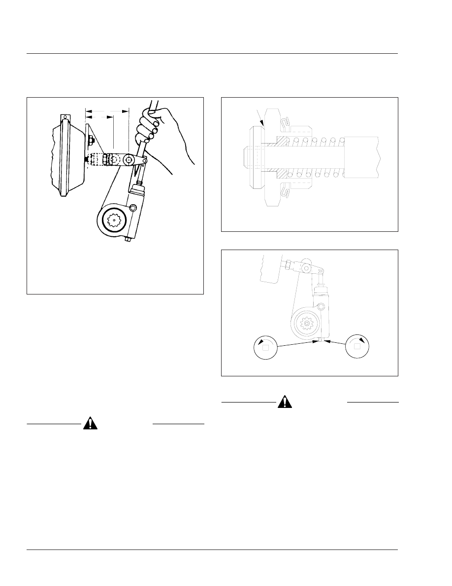
09/27/94 

f420180a

NOTE: For a drum brake, A minus B must equal 5/8 to
3/4 inch (16 to 19 mm). For a disc brake, A minus B
must equal 7/8 to 1-1/8 inch (22 to 29 mm).

A. With the brakes applied, measure this distance.
B. With the brakes released, measure this distance.

Fig. 5, Measuring Free-Stroke

f420693a

09/27/94

A

A. Insert screwdriver here.

Fig. 6, Pull-Pawl Assembly (sectional view)

A

B

f420181a

07/05/95

A. Shorten stroke.

B. Lengthen stroke.

Fig. 7, Brake Stroke Adjusting

Brakes

42

Cargo Maintenance Manual, January 2000

42/6

4.1

With the brakes fully released, measure
the distance from the bottom of the brake
chamber to the center of the large clevis
pin. See

Fig. 5

Ref. A.

4.2

Build air pressure to 100 psi (690 kPa).
Shut down the engine. Fully apply the
brakes, then measure the distance from
the bottom of the brake chamber to the
center of the large clevis pin. See

Fig. 5

,

Ref. B. The difference between the mea-
surements is the brake chamber stroke.

4.3

The brake chamber stroke must be less
than the measurements shown in

Table 1

If the brake chamber stroke is

incorrect, remove the pressure-relief cap-
screw, gasket, pawl spring, and pawl
(

Fig. 4

Ref. 5) from the slack adjuster

housing. If equipped with a pull-pawl as-
sembly (

Fig. 6

), carefully insert a screw-

driver and raise the relief cap about 1/8
inch (3.2 mm).

Maximum Allowable Brake Chamber Stroke With

Meritor Automatic Slack Adjusters

Chamber Size Effective

Area, square inches

Maximum Allowable

Stroke

*

inches (mm) (B minus A)

12

Less than 1–3/8 (35)

16

Less than 1–3/4 (44)

20

Less than 1–3/4 (44)

24

Less than 1–3/4 (44)

24 Long Stroke

Less than 2 (51)

30

Less than 2 (51)

*

Adjust the brakes whenever the applied stroke exceeds the maximum.

Table 1, Maximum Allowable Brake Chamber Stroke

With Meritor Automatic Slack Adjusters

CAUTION

Before turning the adjusting nut, remove the
pressure-relief capscrew, gasket, pawl spring, and
pawl. If equipped with a pull-pawl assembly, raise
the relief cap as instructed. Failure to do so could
strip the teeth on the pawl.

4.4

Turn the adjusting nut one-eighth turn, as
shown in

Fig. 7

Measure the stroke

again, and adjust until correct.

If the stroke varies or remains greater
than the specified range, check the brake
components, including the camshafts,
camshaft bushings, anchor pins, rollers,
chamber brackets, clevis, and clevis pins.
For instructions, see Group 42 of the

Cargo Workshop Manual

.

4.5

If removed, install the pawl, pawl spring,
gasket, and pressure-relief capscrew.
Tighten the capscrew 15 to 20 lbf·ft (20 to
27 N·m). Or, remove the screwdriver from
the pull-pawl assembly (if equipped).

42–09 Automatic Slack

Adjuster Lubrication

Lubricate the slack adjuster using high-temperature,
water-proof grease NLGI grade 1, Texaco Thermotex
EP 1, Shell Darina No. 1, Marathon 528 heavy-duty,
Sunaplex No. 1 EP, Amdex No. 1 EP, or Philube B
No. 1. It should be smooth-textured, corrosion-
resistant grease, free of fillers and abrasives.

42–10 Automatic Slack

Adjuster Inspection

1.

Remove the pressure-relief capscrew, gasket,
pawl spring, and pawl. See

Fig. 4

Ref. 5.

2.

Examine the pawl for grease retention and condi-
tion. If the grease is in good condition, install the
pressure-relief capscrew, gasket, pawl spring,
and pawl. Tighten the capscrew 15 to 20 lbf·ft
(20 to 27 N·m). Lube the slack adjuster through
the grease fitting until lubricant is forced out
through the pressure-relief fitting (or pawl slot). If
a hollow capscrew is used, install and tighten it
15 to 20 lbf·ft (20 to 27 N·m).

If the grease is hardened, or the pawl is dry and
shows extreme wear, remove the slack adjuster.
Disassemble and clean it. Inspect the internal
parts. Install new seals and a new boot when
assembling. Install and lubricate the slack ad-
juster. See Group 42 of the

Cargo Workshop

Manual

.

Brakes

42

Cargo Maintenance Manual, January 2000

42/7

42–11 Air Dryer Check, Bendix

AD–9

During cold-weather operation, check the operation
of the end cover heater and thermostat assembly.

1.

With the ignition on, check for voltage to the
heater and thermostat assembly. Unplug the
electrical connector at the air dryer, and place
the test leads of a voltmeter on each of the pins
of the male connector. If there is no voltage, look
for a blown fuse, broken wires, or corrosion in
the vehicle wiring harness. Check that a good
ground path exists.

2.

Check the thermostat and heater operation. Turn
off the ignition switch and cool the end cover as-
sembly to below 40°F (4°C). Using an ohmmeter,
check the resistance between the electrical pins
in the female connector. The resistance should
be 1.5 to 3.0 ohms for the 12-volt heater assem-
bly.

Warm the end cover assembly to over 90°F
(32°C) and again check the resistance. It should
exceed 1000 ohms. If it does, the thermostat and
heater assembly is operating properly. If it does
not, replace the purge-valve housing assembly,
which includes the heater and thermostat assem-
bly.

42–12 Air Dryer Desiccant

Replacement, Bendix
AD–9

The desiccant change interval may vary from vehicle
to vehicle. Although typical desiccant cartridge life is
three years, many will perform adequately for a
longer period of time. To take maximum advantage of
desiccant life and ensure that replacement occurs
only when necessary, disassemble, clean, and in-
spect the air dryer. Replace the desiccant cartridge.
See Group 42 of the

Cargo Workshop Manual

for

instructions.

42–13 Air Reservoir Automatic

Drain Valve
Disassembly, Clean,
Inspection, and
Lubrication, Bendix
AD–9

Disassemble the drain valve, clean the parts with
mineral spirits, and inspect the parts. Replace all rub-
ber parts and any worn or damaged parts; use only
genuine Bendix replacement parts or kits. Assemble
and install the valve, then check for proper operation
and leakage. See Group 42 of the

Cargo Workshop

Manual

for instructions.

42–14 Air Brake Valve

Disassembly, Clean, and
Inspection, Bendix E–6,
QR–1, and ST–3

Disassemble each brake valve, clean the parts with
mineral spirits, and inspect the parts. Replace all rub-
ber parts and any worn or damaged parts; use only
genuine Bendix replacement parts or kits. Assemble
and install the valves, then check for proper opera-
tion and leakage. See Group 42 of the

Cargo Work-

shop Manual

for instructions.

Brakes

42

Cargo Maintenance Manual, January 2000

42/8

Title of Maintenance Operation (MOP)

MOP Number

Drag Link Lubrication . . . . . . . . . . . . . . . . . . . . . . . . . . . . . . . . . . . . . . . . . . . . . . . . . . . . . . . . . . . . . . . 46–02

Power Steering Reservoir Fluid Level Check. . . . . . . . . . . . . . . . . . . . . . . . . . . . . . . . . . . . . . . . . . . . . . 46–03

Power Steering Reservoir Fluid and Filter Change. . . . . . . . . . . . . . . . . . . . . . . . . . . . . . . . . . . . . . . . . . 46–04

Steering Driveline Lubrication . . . . . . . . . . . . . . . . . . . . . . . . . . . . . . . . . . . . . . . . . . . . . . . . . . . . . . . . . 46–01

Steering Gear Lubrication. . . . . . . . . . . . . . . . . . . . . . . . . . . . . . . . . . . . . . . . . . . . . . . . . . . . . . . . . . . . 46–05

Steering

46

Index, Alphabetical

Cargo Maintenance Manual, January 2000


Content   ..  18  19  20  21   ..