Ford Galaxy / Ford S-MAX. Manual - part 986
 

  Index      Ford     Ford Galaxy / Ford S-MAX - service repair manual 2006 year


Search            


Content   ..  984  985  986  987   ..


Ford Galaxy / Ford S-MAX. Manual - part 986


Is the resistance greater than 10,000 ohms? 
Yes 

GO to CC2

.  

No 

REPAIR circuits VDB06AB (GY/OG) and VDB07H 
(VT/OG). REPEAT the self-test, CLEAR the DTCs. 
REACTIVATE the system.  

CC2: CHECK THE RCM COMMUNICATION BUS CIRCUIT FOR A SHORT CIRCUIT TO 
GROUND

WARNING: To avoid accidental deployment, the RCM backup power supply must be 

depleted. Wait at least one minute after disconnecting the battery ground cable(s) before 
commencing any repair or adjustment to the SRS, or any component(s) adjacent to the 
SRS sensors. Failure to follow these instructions may result in personal injury. 

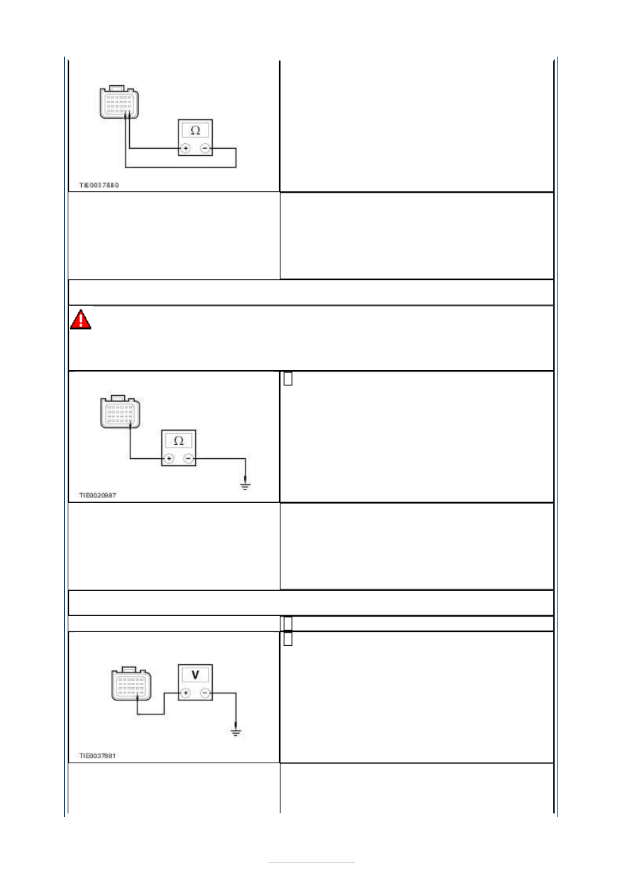
Measure the resistance between the RCM 
C2R114-A pin 19, circuit VDB06AB (GY/OG), 

harness side and ground. 

Is the resistance greater than 10,000 ohms? 
Yes 

GO to CC3

.  

No 

REPAIR circuit VDB06AB (GY/OG). REPEAT the 
self-test, CLEAR the DTCs. REACTIVATE the 
system.  

CC3: CHECK THE RCM COMMUNICATION BUS CIRCUIT FOR A SHORT CIRCUIT TO 
BATTERY OR IGNITION

Ignition switch in position II. 

Measure the voltage between the RCM C2R114-A 
pin 20, circuit VDB07H (VT/OG), harness side 

and ground. 

Is any voltage present? 
Yes 

REPAIR circuit VDB07H (VT/OG). REPEAT the 


self-test, CLEAR the DTCs. REACTIVATE the 
system.  

No 

REPEAT the self-test, CLEAR the DTCs. 
REACTIVATE the system.  

PINPOINT TEST CD : DTC U3000 13: AIR BAG DIAGNOSTIC MONITOR 
GROUND CIRCUIT OPEN 

TEST CONDITIONS

DETAILS/RESULTS/ACTIONS

CD1: CHECK THE RCM GROUND CIRCUIT

WARNING: To avoid accidental deployment, the RCM backup power supply must be 

depleted. Wait at least one minute after disconnecting the battery ground cable(s) before 
commencing any repair or adjustment to the SRS, or any component(s) adjacent to the 
SRS sensors. Failure to follow these instructions may result in personal injury. 
NOTE: CHECK that the PAD switch is in the air bag live position before carrying out this 
test. 

Deactivate the SRS.  

Check the RCM electrical connectors. 

Are the RCM electrical connectors fully engaged? 
Yes 

Check the RCM installation.  
REFER to: 

Restraints Control Module (RCM)

 (501-20B Supplemental 

Restraint System, Removal and Installation). 
REPEAT the self-test, CLEAR the DTCs. REACTIVATE the system. If the 
DTC remains, INSTALL a new RCM.  
REFER to: 

Restraints Control Module (RCM)

 (501-20B Supplemental 

Restraint System, Removal and Installation). 

No 

CONNECT the RCM electrical connectors. REPEAT the self-test, CLEAR 
the DTCs. REACTIVATE the system.  

Supplemental Restraint System - 
Clockspring Adjustment

S-MAX/Galaxy 2006.5 (02/2006-)


Print


General Procedures 

WARNINGS: 

If there is a break between installing the clockspring and steering wheel rotation 

sensor assembly and installing the steering wheel, the centralizing of the clockspring 
must be repeated. 

If the centralization of the clockspring is in doubt, the centralizing of the clockspring 

must be repeated. 

CAUTION: The clockspring and steering wheel rotation sensor assembly must not be 

rotated in a couterclockwise direction more than the specified revolutions. 
NOTE: Make sure that the road wheels are in the straight ahead position. 

1.   

1. Turn the clockspring rotor in a clockwise 

direction until a resistance is felt. 

2. Turn the clockspring in a counterclockwise 

direction 2.5 revolutions. 

2.   

Check to see if the yellow roller is visible in 
the clockspring window. 
Using a suitable piece of tape, secure the 
clockspring rotor to the clockspring body. 


Supplemental Restraint System - 
Deployed Air Bag Disposal

S-MAX/Galaxy 2006.5 (02/2006-)


Print


General Procedures 

WARNING: After deployment, the air bag module surface may contain deposits of 

sodium hydroxide, a product of the gas generate combustion, that is irritating to the skin. 
Use protective gloves when handling any deployed air bag module. Failure to follow this 
instruction may result in personal injury. 

1. Remove the deployed air bag module(s). For 

additional information, refer to the relevant 
procedure in this section. 

2. Seal the deployed air bag module(s) in the 

packaging from the new air bag module(s) or a 
suitable polythene bag, and then dispose of in 
accordance with local contaminated waste 
regulations. 


Content   ..  984  985  986  987   ..