Ford Galaxy / Ford S-MAX. Manual - part 976
 

  Index      Ford     Ford Galaxy / Ford S-MAX - service repair manual 2006 year


Search            


Content   ..  974  975  976  977   ..


Ford Galaxy / Ford S-MAX. Manual - part 976


Deactivate the SRS.  

Disconnect Crash Sensor C1R213. 

Disconnect RCM C2R114-A. 

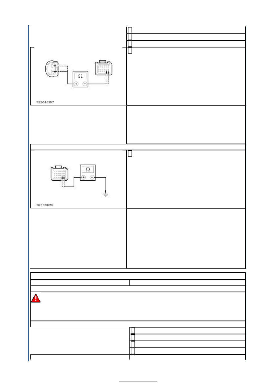
Measure the resistance between the: 

RCM C2R114-A pin 13, circuit RR129A 
(YE/GY), harness side and the crash sensor 
C1R213 pin 2, circuit RR129A (YE/GY), 
harness side.  
RCM C2R114-A pin 14, circuit VR213A 
(VT/GN), harness side and the crash sensor 
C1R213 pin 1, circuit VR213A (VT/GN), 
harness side. 

Are the resistances less than 5 ohms? 
Yes 

GO to AJ2

.  

No 

REPAIR circuit VR213A (VT/GN) or circuit 
RR129A (YE/GY). REPEAT the self-test, CLEAR 
the DTCs. REACTIVATE the system.  

AJ2: CHECK THE CRASH SENSOR FOR A SHORT CIRCUIT TO GROUND

Measure the resistance between the: 

RCM C2R114-A pin 13, circuit RR129A 
(YE/GY), harness side and ground.  
RCM C2R114-A pin 14, circuit VR213A 
(VT/GN), harness side and ground. 

Are the resistances greater than 10,000 ohms? 
Yes 

INSTALL a new crash sensor.  
REFER to: 

Crash Sensor

 (501-20B Supplemental 

Restraint System, Removal and Installation). 
REPEAT the self-test, CLEAR the DTCs. 
REACTIVATE the system. 

No 

REPAIR circuit VR213A (VT/GN) or circuit 
RR129A (YE/GY). REPEAT the self-test, CLEAR 
the DTCs. REACTIVATE the system.  

PINPOINT TEST AK : DTC B00D5 12: PAD INDICATOR SHORT TO BATTERY 

TEST CONDITIONS

DETAILS/RESULTS/ACTIONS

AK1: CHECK THE PAD INDICATOR TO RCM CIRCUIT

WARNING: To avoid accidental deployment, the RCM backup power supply must be 

depleted. Wait at least one minute after disconnecting the battery ground cable(s) before 
commencing any repair or adjustment to the SRS, or any component(s) adjacent to the 
SRS sensors. Failure to follow these instructions may result in personal injury. 
NOTE: Use a digital multimeter for all electrical measurements. 

Deactivate the SRS.  

Disconnect PAD Indicator C2R224-A. 

Disconnect RCM C2R114-A. 

Ignition switch in position II. 


Measure the voltage between the RCM 
C2R114-A pin 17, circuit CR116A (GN/WH), 

harness side and ground. 

Is any voltage present? 
Yes 

REPAIR circuit CR116A (GN/WH). REPEAT the 
self-test, CLEAR the DTCs. REACTIVATE the 
system.  

No 

INSTALL a new PAD indicator. REPEAT the self-
test, CLEAR the DTCs. REACTIVATE the 
system.  

PINPOINT TEST AL : DTC B00D5 14: PAD INDICATOR SHORT TO GROUND 
OR OPEN CIRCUIT 

TEST CONDITIONS

DETAILS/RESULTS/ACTIONS

AL1: CHECK FOR CONTINUITY BETWEEN THE RCM AND GROUND

WARNING: To avoid accidental deployment, the RCM backup power supply must be 

depleted. Wait at least one minute after disconnecting the battery ground cable(s) before 
commencing any repair or adjustment to the SRS, or any component(s) adjacent to the 
SRS sensors. Failure to follow these instructions may result in personal injury. 
NOTE: Use a digital multimeter for all electrical measurements. 

Deactivate the SRS.  

Disconnect RCM C2R114-A. 

Disconnect PAD Indicator C2R224-A. 

Measure the resistance between the RCM 
C2R114-A pin 17, circuit CR116A (GN/WH), 

harness side and ground.  

Is the resistance greater than 10,000 ohms? 
Yes 

GO to AL2

.  

No 

REPAIR circuit CR116A (GN/WH). REPEAT the 
self-test, CLEAR the DTCs. REACTIVATE the 
system.  

AL2: CHECK FOR CONTINUITY BETWEEN THE PAD INDICATOR AND THE RCM 

Measure the resistance between the RCM 
C2R114-A pin 17, circuit CR116A (GN/WH), 

harness side and the PAD indicator C2R224-A pin 
4, circuit CR116A (GN/WH), harness side. 


Is the resistance less than 5 ohms? 
Yes 

GO to AL3

.  

No 

REPAIR circuit CR116A (GN/WH). REPEAT the 
self-test, CLEAR the DTCs. REACTIVATE the 
system.  

AL3: CHECK THE PAD INDICATOR SUPPLY CIRCUIT 

Ignition switch in position II. 

Measure the voltage between the PAD indicator 
C2R224-A pin 1, circuit CBP04N (VT), harness 

side and ground. 

Is the voltage greater than 10 volts? 
Yes 

INSTALL a new PAD indicator. REPEAT the self-
test, CLEAR the DTCs. REACTIVATE the system.  

No 

REPAIR circuit CBP04N (VT). REPEAT the self-
test, CLEAR the DTCs. REACTIVATE the system.  

PINPOINT TEST AM : DTC B00DF 01: PAD SWITCH 

TEST CONDITIONS

DETAILS/RESULTS/ACTIONS

AM1: CHECK THE PAD SWITCH CIRCUIT FOR LOW RESISTANCE

WARNING: To avoid accidental deployment, the RCM backup power supply must be 

depleted. Wait at least one minute after disconnecting the battery ground cable(s) before 
commencing any repair or adjustment to the SRS, or any component(s) adjacent to the 
SRS sensors. Failure to follow these instructions may result in personal injury. 
NOTE: Use a digital multimeter for all electrical measurements. 

Deactivate the SRS.  

Disconnect RCM C2R114-A. 

Measure the resistance between the RCM 
C2R114-A pin 18, circuit CR224A (GN), harness 

side and the RCM C2R114-A pin 21, circuit 
CR225A (YE), harness side.  


Is the resistance greater than 10,000 ohms? 
Yes 

GO to AM2

.  

No 

GO to AM5

.  

AM2: CHECK FOR CONTINUITY BETWEEN THE RCM AND THE PAD SWITCH - 
ACTIVATION CIRCUIT

Disconnect PAD Switch C2R224-B. 

Measure the resistance between the RCM 
C2R114-A pin 18, circuit CR224A (GN), harness 

side and the PAD switch C2R224-B pin 6, circuit 
CR224A (GN), harness side.  

Is the resistance less than 5 ohms? 
Yes 

GO to AM3

.  

No 

REPAIR circuit CR224A (GN). REPEAT the self-
test, CLEAR the DTCs. REACTIVATE the system.  

AM3: CHECK FOR CONTINUITY BETWEEN THE RCM AND THE PAD SWITCH - 
DEACTIVATION CIRCUIT

Measure the resistance between the RCM 
C2R114-A pin 21, circuit CR225A (YE), harness 

side and the PAD switch C2R224-B pin 4, circuit 
CR225A (YE), harness side. 

Is the resistance less than 5 ohms? 
Yes 

GO to AM4

.  

No 

REPAIR circuit CR225A (YE). REPEAT the self-
test, CLEAR the DTCs. REACTIVATE the system.  

AM4: CHECK FOR CONTINUITY BETWEEN THE RCM AND THE PAD SWITCH - COMMON 
CIRCUIT

Measure the resistance between the RCM 
C2R114-A pin 13, circuit RR129A (YE/GY), 

harness side and the PAD switch C2R224-B pin 5, 
circuit RR129C (YE/GY), harness side. 

Is the resistance less than 5 ohms? 
Yes 

INSTALL a new PAD switch.  
REFER to: 

Passenger Air Bag Deactivation (PAD) 

Switch

 (501-20B Supplemental Restraint System, 

Removal and Installation). 
REPEAT the self-test, CLEAR the DTCs. 


Content   ..  974  975  976  977   ..