Ford Galaxy / Ford S-MAX. Manual - part 710
 

  Index      Ford     Ford Galaxy / Ford S-MAX - service repair manual 2006 year


Search            


Content   ..  708  709  710  711   ..


Ford Galaxy / Ford S-MAX. Manual - part 710


Description 

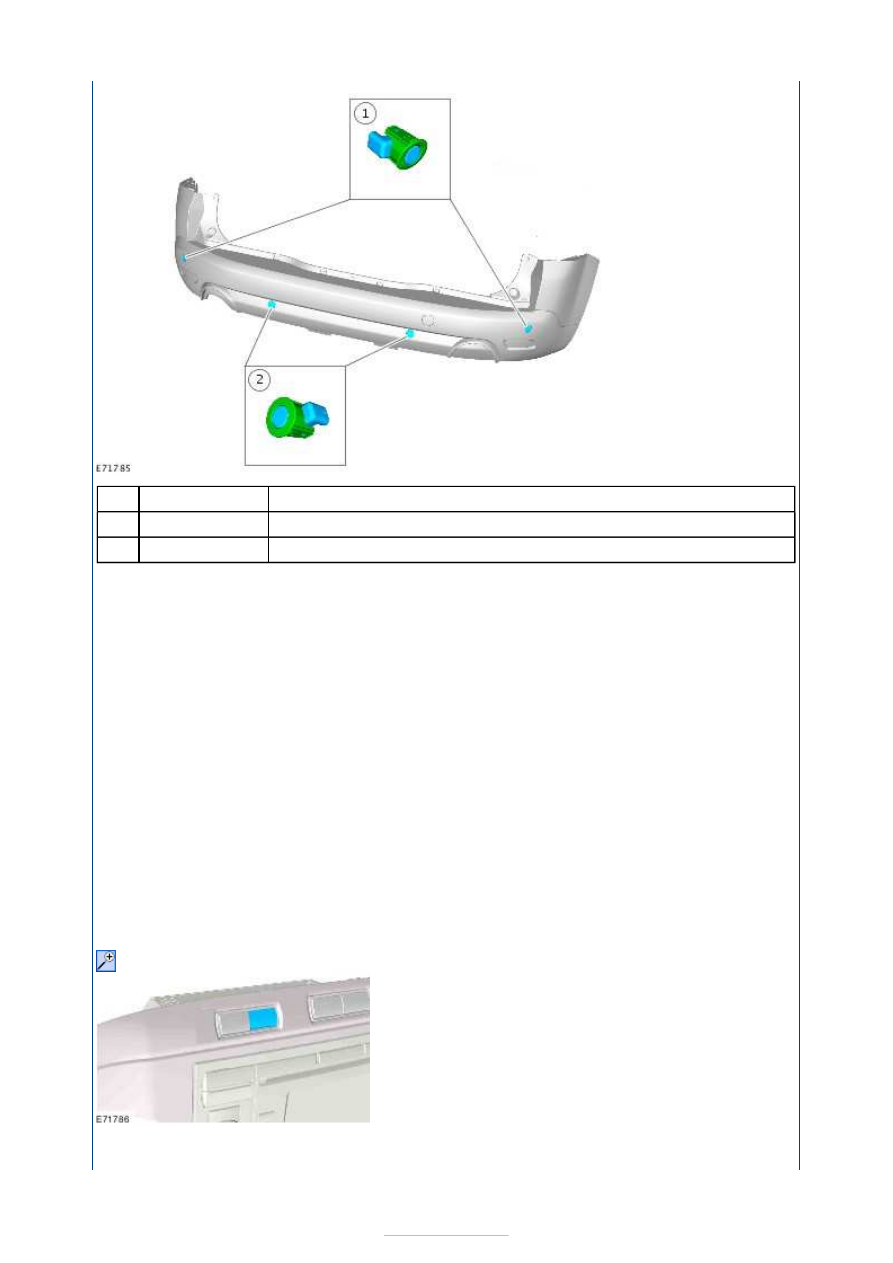
Rear outer parking aid sensor(s) 

Rear inner parking aid sensor(s) 

The parking aid sensor comprises of a sensor and a holder. The holder makes sure that 
each parking aid sensor is correctly orientated in relation to its location in the rear bumper. 

Each parking aid sensor has a three pin connector which connects with the rear bumper 
wiring harness, which in turn is connected to the main body wiring harness. Three pins 
provide for power supply, ground and signal lines to and from the parking aid module. 

Each parking aid sensor comprises of the following: 

a plastic housing  
an aluminium membrane which contains a piezo electric disc  
a decoupling ring which may be a separate component from the sensor or overmoulded 
to the sensor membrane 

The disc resonates at a frequency of ca. 50kHz, producing the ultrasonic output. The disc 
also receives the reflected echo signal from any objects within range. 

The parking aid module controls the operation of each parking aid sensor using a digital 
output on the signal line. The parking aid module controls the parking aid sensor in one of 
two modes; combined transmitter and receiver mode or receiver mode only. 

Parking aid switch 

The parking aid switch is located in the instrument panel, above the audio unit or 

Item

1

2


Part Number

-

-


navigation system display module. The parking aid switch is the left-hand side switch with 
an integral LED. 

The parking aid switch is a non-latching push switch which allows the driver to select the 
parking aid system on or off. When pressed, the parking aid switch momentarily connects a 
ground to the parking aid module. The LED indicates when the parking aid system is active. 
The LED is controlled by the parking aid module. 

The parking aid switch allows the driver to disable the parking aid system when reverse 
gear is selected or to activate the parking aid sensors when not in reverse gear. 

If a concern exists in the parking aid system, the LED flashes for 3 seconds when the 
reverse gear is selected or the driver selects the parking aid sensors on, using the parking 
aid switch. 

Front parking aid sensor 


Description 

Front inner parking aid sensor(s) 

Front outer parking aid sensor(s) 

The parking aid sensor comprises of a sensor and a holder. The holder makes sure that 
each parking aid sensor is correctly orientated in relation to its location in the front bumper. 

Each parking aid sensor has a three pin connector which connects with the front bumper 
wiring harness, which in turn is connected to the main body wiring harness. Three pins 
provide for power supply, ground and signal lines to and from the parking aid module. 

Each parking aid sensor comprises of the following: 

a plastic housing  
an aluminium membrane which contains a piezo electric disc  
a decoupling ring which may be a separate component from the sensor or overmoulded 
to the sensor membrane 

The disc resonates at a frequency of ca. 50kHz, producing the ultrasonic output. The disc 
also receives the reflected echo signal from any objects within range. 

The parking aid module controls the operation of each parking aid sensor using a digital 
output on the signal line. The parking aid module controls the parking aid sensor in one of 

Item

1

2


Part Number

-

-

two modes; combined transmitter and receiver mode or receiver mode only. 

Distance calculation 

Front parking aid sensors 

The maximum detection range for the front parking aid sensors is 800 mm (31 inches) for 
the central parking aid sensors and 600 mm (23.5 inches) for the corner parking aid 
sensors. 

Rear parking aid sensors 

The maximum detection range for the rear parking aid sensors is 1800 mm (70 inches) for 
the central parking aid sensors and 600 mm (23.5 inches) for the corner parking aid 
sensors. 


Parking Aid - Parking Aid

S-MAX/Galaxy 2006.5 (02/2006-)


Print


Diagnosis and Testing 

Principle of Operation 

For a detailed description of the parking aid system,  
REFER to: 

Parking Aid

 (413-13 Parking Aid, Description and Operation). 

Inspection and Verification 

CAUTION: Diagnosis by substitution from a donor vehicle is NOT acceptable. 

Substitution of control modules does not guarantee confirmation of a fault, and may also 
cause additional faults in the vehicle being tested and/or the donor vehicle. 

1. 1. Verify the customer concern. 

2. 2. Visually inspect for obvious signs of electrical damage. 

NOTE: Particular attention should be paid to the following items where Diagnostic Trouble 
Codes (DTCs) may not be logged: 

Check for contamination (e.g. foreign matter, grime, frosting, ice) around the parking aid 
sensors, if so clean as necessary.  
Check for the correct installation and alignment of the sensors to the bumper cover.  
Spurious detection of the ground may occur during front system operation on an up-
slope. 

Visual Inspection 

3. 3. If an obvious cause for an observed or reported concern is found, correct the cause 

(if possible) before proceeding to the next step. 

4. 4. If the cause is not visually evident, check for DTCs and refer to the DTC Index 

Chart. 

DTC Index Chart 

NOTE: Generic scan tools may not read the DTCs listed, or may read only five digit codes. 
Match the five digits from the scan tool to the first five digits of the seven digit code listed 
to identify the concern (the last two digits give additional information read by the 
manufacturer approved diagnostic system). 
NOTE: When carrying out voltage or resistance tests, always use a digital multimeter 
(DMM) accurate to three decimal places, and with an up-to-date calibration certificate. 
When testing resistance always take the resistance of the DMM leads into account. 
NOTE: Check and rectify basic concerns before beginning diagnostic routines involving 

Electrical

Fuse(s)  

Relay(s)  

Wiring Harness  

Electrical connector(s)  

Front parking aid sensor(s) and retainers  

Rear parking aid sensor(s) and retainers  

Front parking aid speaker  

Rear parking aid speaker  

Parking aid switch and LED  

Reversing lamp switch  

Parking aid module 


Content   ..  708  709  710  711   ..