Ford Galaxy / Ford S-MAX. Manual - part 483
 

  Index      Ford     Ford Galaxy / Ford S-MAX - service repair manual 2006 year


Search            


Content   ..  481  482  483  484   ..


Ford Galaxy / Ford S-MAX. Manual - part 483


Transmission components 

Ravigneaux planetary gearset 

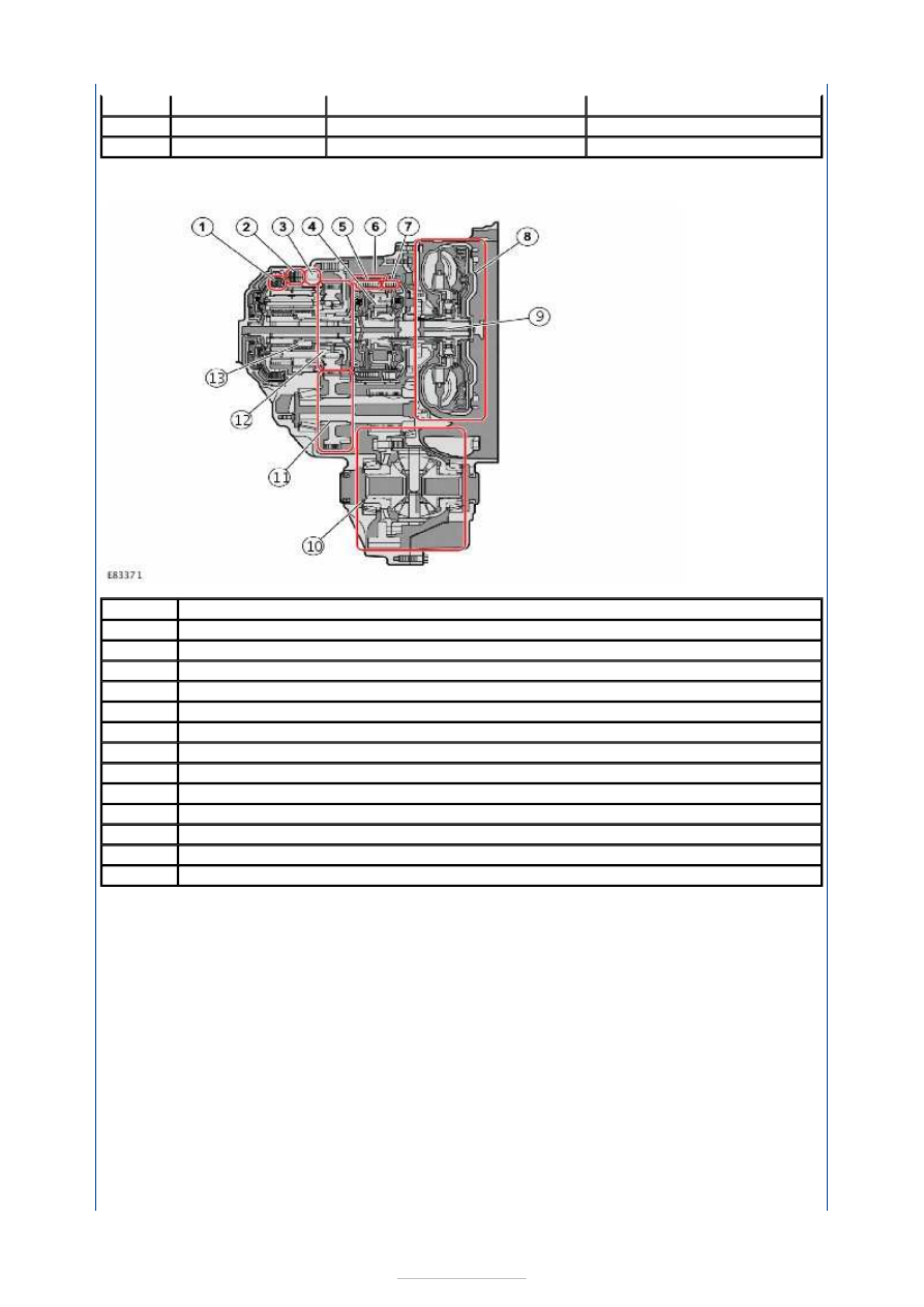
One of the special features of the AWF21 transmission is its Ravigneaux planetary gearset. 

The Ravigneaux planetary gearset has the following features: 

It offers the possibility of more gears than a conventional planetary gearset.  
Compact design (space-saving) in relation to the available transmission ratios.  
Two sun gears with different diameters  
Two sets of planetary gears - inner and outer. The inner planetary gears are in constant 
mesh with the smaller, rear sun gear and with the outer planetary gears. The outer 
planetary gears are in constant mesh with the ring gear and the larger, front sun gear.  
The planetary gears are all fitted on a joint planetary gear holder. 

Operation 

The transmission ratios are achieved via the following combinations of locked and/or 
coupled components. The table shows the principle of obtaining a high ratio (1), a low ratio 

5th

0,859

2,86

3,22

6th

0,686

2,28

2,57

Reverse

3,394

11,30

12,73

Item

Component

1

C2 clutch

2

B2 brake

3

F1 freewheel

4

Front planetary gearset

5

C1 clutch

6

B1 brake

7

C3 clutch

8

TORQUE CONVERTER

9

Differential unit

10

Driven gear wheel of the intermediate stage

11

Driving gear wheel of the intermediate stage

12

Ravigneaux planetary gear set

13

Turbine shaft


(6) and a reverse rotation (i.e. reverse gear with a high ratio). 


Description 

Ring gear 

Long planet gear 

Small planet gear 

Short planet gear 

Transmission input shaft 

Large sun gear 

On the AWF21 transmission the Ravigneaux planetary gearset is connected in series with a 
conventional planetary gearset. The conventional planetary gearset can generate a speed 
reduction on the two sun gears of the Ravigneaux planetary gearset for gears 1 to 5 and for 
reverse gear. 

Electrical control 

The following components are part of the control system for the automatic 
transmission: 

TCM. Controls activation and deactivation of the solenoid valves by processing the input 
signals from, among others the speed sensor and rotational speed sensor of the 
transmission, as well as the temperature sensor. It also saves adaptive data, DTCs and 
frozen values for diagnosis.  
Gearshift position sensor, integrated in the TCM.  
Solenoid valves S1 and S2. Primarily control engine braking in 1st gear.  
Solenoid valve SLU. Controls the lockup function, and is also used during certain 
gearshift processes.  

Item

1

2

3

4

5

6

Gear / ratio

Input torque

Locked

Output torque

1

Small sun gear

Planetary gear holder

RIng gear

2

Small sun gear

Large sun gear

RIng gear

3

Small sun gear and large sun gear

No component

Ring gear

4

Small sun gear and planetary gear holder

No component

Ring gear

5

Large sun gear and planetary gear holder

No component

RIng gear

6

Planetary gear holder

Large sun gear

RIng gear

Reverse.

Large sun gear

Planetary gear holder

RIng gear


Part Number

-

-

-

-

-

-

Solenoid valve SLT. Controls the transmission system pressure.  
The solenoid valves SLC1, SLC2 and SLC3 control which clutches are used.  
Solenoid valve SLB1. Controls the use of brake B1.  
Rotational speed sensor, input shaft  
Output shaft rotational speed sensor  
Oil temperature sensor  
GSM (Gear Selector Module), in the gear selector housing. Provides information to the 
TCM about the desired driving mode, etc. Shift select mode and sport mode W.  
Hydraulic system with oil pump, torque converter, hydraulic control housing and oil 
cooler.  
A front planetary gearset and a rear planetary gearset, the transmission ratios of which 
are controlled by clutches and brakes. 

Solenoid valves 

Item

Component

1

Oil temperature sensor

2

Solenoid valve SLU

3

Solenoid valve SLC3

4

Solenoid valve SLB1

5

Input shaft rotational speed sensor

6

Output shaft rotational speed sensor

7

Solenoid valve S1

8

Solenoid valve S2

9

Solenoid valve SLT

10

Solenoid valve SLC2

11

Solenoid valve SLC1

12

transmission control module


Automatic Transmission/Transaxle - 
Vehicles With: 6-Speed Automatic 
Transaxle - AWF21 - Automatic 
Transmission

S-MAX/Galaxy 2006.5 (02/2006-)


Print


Diagnosis and Testing 

Construction features, transmission differential side 

WARNINGS: 

The ESD protection measures must be adhered to without fail, as otherwise the 

transmission electronics could be destroyed. 

Electrical connectors to and from the automatic transmission control electronics must 

only be separated or connected when no voltage is present. 

Because of bodily electrostatic charge, connectors must not be disturbed, as this may 

cause damage to the transmission control electronics. 
NOTE: In order for the diagnosis of the automatic transmission to be meaningful, all other 
systems such as the PCM, IC and ABS must be operating correctly, because through the 
CAN databus they may have an effect on the TCM and therefore on the transmission 
control. 
NOTE: Electrical faults which appear - even only momentarily - when the ignition is 
switched on, will be stored in the fault memory of the relevant control unit and may have 
effects on the control system. Loose connections and fuses or connectors which have 
been removed or disconnected for testing purposes all count as electrical faults. 

Introduction 

WARNING: Adhere to the ESD protection measures listed below without fail, as 

otherwise the transmission control electronics could be destroyed 
NOTE: Always take into account TSBs and OASIS messages. 
NOTE: Do not take any short cuts or assume that critical checks or adjustments have 
already been made. 
NOTE: Follow the test procedure described in the WDS/IDS exactly. In this way, test 
steps or important component tests are prevented from being overlooked. 

Troubleshooting an electronically controlled automatic transaxle is simplified by using the 
proven method of diagnosis. One of the most important things to remember is that there is 
a definite procedure to follow. 

Details of ESD protection 

When dealing with the mechatronics, for example during a repair, suitable protective 
measures must be taken, especially ESD protection. 

The term ESD means: Electro Static Discharge. 

A person who is electrostatically charged and not earthed carries a voltage field with them, 
and so endangers "electrostatically sensitive components" which are contained in the 
control electronics. Carelessness when working on the transmission, touching the contacts 
of the central connector with the hand or making measurements using a multimeter will 
destroy the control electronics. 

Preliminary inspection 

NOTE: Many concerns with an automatic transmission are caused by incorrect operating 
conditions or operating error on the part of the driver. It is therefore very important to 
include the environment when making a diagnosis. 

Apply the parking brake and move the selector lever to the "P" position when: 


Content   ..  481  482  483  484   ..