Ford Galaxy / Ford S-MAX. Manual - part 441
 

  Index      Ford     Ford Galaxy / Ford S-MAX - service repair manual 2006 year


Search            


Content   ..  439  440  441  442   ..


Ford Galaxy / Ford S-MAX. Manual - part 441


Engine Emission Control - 2.0L Duratorq-
TDCi (85kW/115PS) - DW/2.0L Duratorq-
TDCi (100kW/136PS) - DW/2.0L Duratorq-
TDCi (103kW/140PS) - DW, Emission 
Requirements: Stage IV - Exhaust Manifold 
to Exhaust Gas Recirculation (EGR) Valve 
Tube

S-MAX/Galaxy 2006.5 (02/2006


Print

Removal and Installation 

Removal 

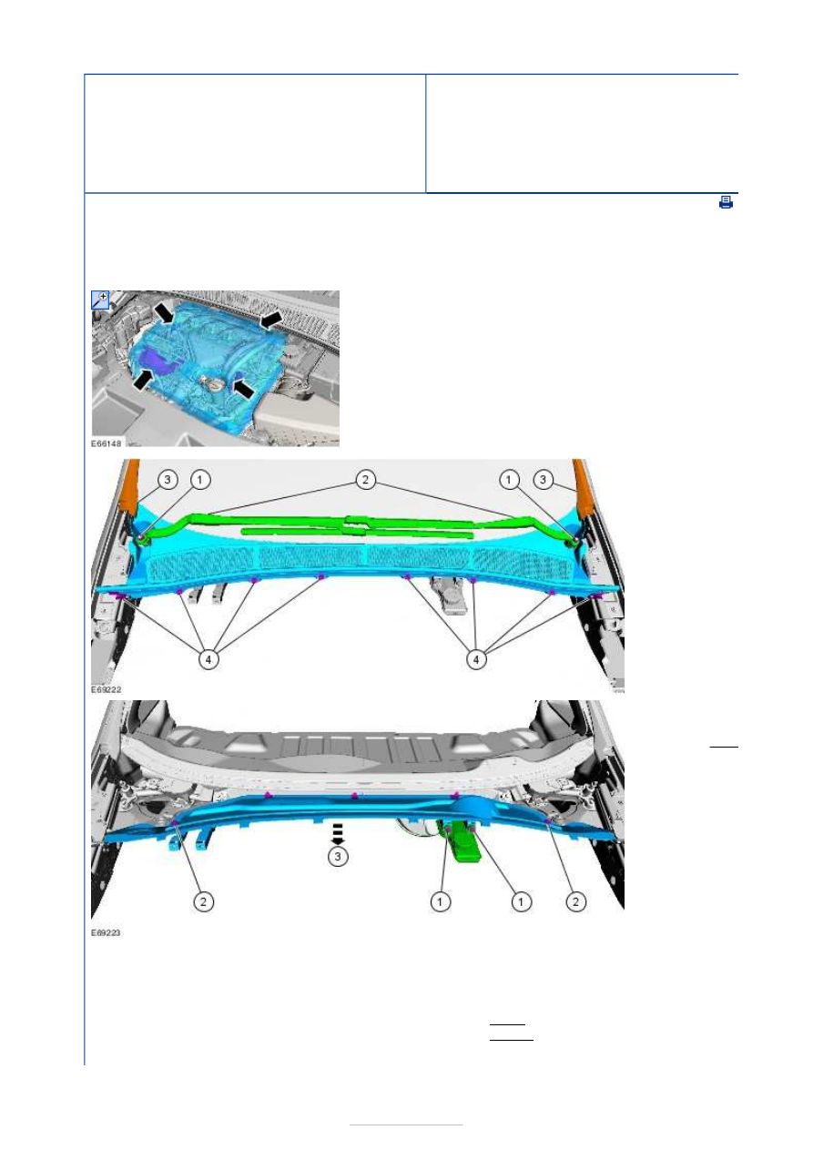
NOTE: Removal steps in this procedure may contain installation details. 

1.  

2.   

1. Torque: 

22 Nm

3. Detach 

the A
pillar 
exterior 
trim 
panel 
lower 
clips.

3.   

2. Torque: 

10 Nm

4.

NOTE: Note the orientation of the clamp to aid 
installation. 
NOTE: The gaskets are to be reused unless 
damaged. 

1. Torque: 5 Nm 
2. Torque: 10 Nm 
3. Discard the clamp. 


Installation 

4. Torque: 10 Nm 

1.

NOTE: Make sure that a new clamp is installed. 
NOTE: Make sure that the clamp is installed to the 
same orientation as when removed. 

To install, reverse the removal procedure. 


Engine Emission Control - 2.2L Duratorq-
TDCi (129kW/175PS) - DW - Engine 
Emission Control—

S-MAX/Galaxy 2006.5 (02/2006-)


Print


Diagnosis and Testing 

General Equipment 

Principles of Operation 

Exhaust Gas Recirculation (EGR) system 

To maintain the standards of low exhaust emission levels required of todays engines, the 
EGR system on this engine is fully electronically controlled. 

The EGR valve is a proportional electric motor controlled directly by a duty-cycle signal 
from the powertrain control module (PCM). Integrated into the EGR valve is a valve position 
sensor. The signal from the EGR valve position sensor allows for the precise control of the 
timing and the quantity of exhaust gas to be recirculated. If the EGR valve becomes 
inoperative or fails to close completely, the PCM will raise a diagnostic trouble code (DTC) 
and the instrument cluster malfunction indicator lamp (MIL) will be illuminated. At the end 
of each drive cycle the PCM drives the EGR valve to the fully open and fully closed positions 
several times. This assists with cleaning the EGR valve. 

If a new EGR valve is installed. The base setting (closed position) value must be configured 
to the PCM using the Ford approved diagnostic tool. If the base setting is not configured to 
the PCM, the setting from the previous EGR valve will be used and the control function of 
the EGR system will be incorrect. 

The EGR system is fitted with an EGR cooler. The EGR cooler reduces the temperature of 
the exhaust gasses being returned to the intake system. By reducing the EGR temperature, 
the intake air charge density is not adversely affected, so maintaining the optimum fuelling 
characteristics. 

Positive Crankcase Ventilation (PCV) system 


Description 

PCV valve diaphragm 

PCV valve 

The PCV system is made up of a crankcase vent oil separator chamber connected to the 
crankcase by a hose. The crankcase vent oil separator chamber is an integral part of the 
intake manifold.  

The crankcase pressure is controlled by a diaphragm operated PCV valve built into the 
crankcase vent oil separator. As the pressure in the crankcase vent oil separator reduces, 
the diaphragm valve closes against the force of the PCV valve spring, so closing the PCV 
valve. As the crankcase pressure rises, the PCV valve is pushed open assisted by the PCV 
valve spring. This allows the positive crankcase gasses to be scavenged by the air intake 
system. 

Ford approved diagnostic tool

Item

1

2


Part Number

-

-

Inspection and Verification 

1. 1. Verify the customer concern. 

2. 2. Visually inspect for obvious signs of mechanical or electrical damage. 

Visual Inspection Chart 

3. 3. If an obvious cause for an observed or reported concern is found, correct the cause 

(if possible) before proceeding to the next step. 

4. 4. If the cause is not visually evident, verify the symptom and refer to the DTC Index 

Chart. 

5. 5. If no DTCs related to the concern are retrieved, proceed to the Symptom Chart to 

continue diagnosis. 

Diagnostic Trouble Code (DTC) Index Chart 

Symptom Chart 

Mechanical

Electrical

Exhaust gas recirculation (EGR) valve  

EGR tube  

EGR cooler  

EGR tube clamp  

Gasket  

PCV hose  

Crankcase vent oil separator 

Electrical connector  

Wiring harness 

DTC

Description

Possible 

Source

Action

P1412

MIL illuminated

EGR valve

REFER to Excessive exhaust black smoke in 

the Symptom Chart

P0404

MIL illuminated

EGR valve

REFER to Excessive exhaust black smoke in 

the Symptom Chart

P1335 Powertrain warning indicator 

illuminated

EGR valve

REFER to Excessive exhaust black smoke in 

the Symptom Chart

Symptom

Possible 

Sources

Action

Excessive 
exhaust 
black 
smoke

EGR valve. 

*

Using the Ford approved diagnostic tool, CHECK the PCM 

calibration. If necessary UPDATE the PCM calibration to the 
latest level. Using the Ford approved diagnostic tool, 
TOOLBOX/POWERTRAIN SERVICE FUNCTIONS/COMPONENT 
OR PARAMETER RESET/EGR RE-CALIBRATION, RESET the EGR 
valve. Carry out a road test, if the concern persists GO to 
Pinpoint Test 

A. 


*

Excessive 
crankcase 
pressure

Blocked or 

damaged PCV 
hose(s). 

Blocked 

crankcase 
vent oil 
separator. 

*

*

GO to Pinpoint Test 

B. 


*

Worn or 

damaged 
engine 
components. 

*

REFER to: 

Engine

 (303-01G Engine - 2.2L Duratorq-TDCi 

(129kW/175PS) - DW, Diagnosis and Testing). 

*


Content   ..  439  440  441  442   ..