Ford Galaxy / Ford S-MAX. Manual - part 423
 

  Index      Ford     Ford Galaxy / Ford S-MAX - service repair manual 2006 year


Search            


Content   ..  421  422  423  424   ..


Ford Galaxy / Ford S-MAX. Manual - part 423


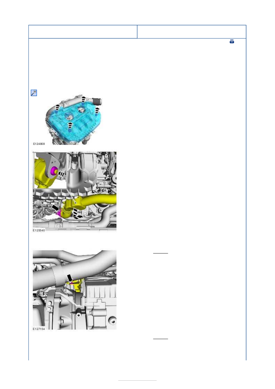
Starting System - 2.0L EcoBoost SCTi 
(149kW/203PS) - MI4 - Starter Motor

S-MAX/Galaxy 2006.5 (02/2006-)


Print


Removal and Installation 

Removal 

NOTE: Removal steps in this procedure may contain installation details. 

1. Refer to: 

Battery Disconnect and Connect

 (414-

01 Battery, Mounting and Cables, General 
Procedures). 

2.  

3.  

4. Refer to: 

Lifting

 (100-02 Jacking and Lifting, 

Description and Operation). 

5. Torque: 12 Nm 

6. Torque: 12 Nm 


Installation 

7. Torque: 

1 48 Nm 
2 12 Nm 
3 10 Nm 

8.

NOTE: Make sure that a new component is 
installed. 

1. To install, reverse the removal procedure. 


Starting System - 2.0L EcoBoost SCTi 
(149kW/203PS) - MI4 - Start Inhibit 
Switch

S-MAX/Galaxy 2006.5 (02/2006-)


Print


Removal and Installation 

Removal 

CAUTION: Make sure that the clutch pedal remains in the rest position. 

Installation 

CAUTION: Make sure that the clutch pedal remains in the rest position. 

1.  

1. To install, reverse the removal procedure. 


Starting System - 2.5L Duratec 
(162kW/220PS) - VI5 - Starting System

S-MAX/Galaxy 2006.5 (02/2006-)


Print


Diagnosis and Testing 

General Equipment 

Principles of Operation 

The starter motor function is controlled by a starter relay. The starter relay is operated by 
the ignition switch.  

Battery voltage is supplied to the ignition switch from battery junction box (BJB) fuse F17. 
When the ignition switch is turned to position III, battery voltage is supplied to the starter 
relay coil. The starter relay coil circuit is completed by a ground circuit through the 
powertrain control module (PCM). The ground circuit will only be available when the PCM 
receives the correct signal from the passive anti-theft system (PATS). 

When the starter relay coil is energized, the starter relay contacts close and battery voltage 
is supplied to the starter motor solenoid circuit from BJB fuse F15. The starter motor 
solenoid circuit is completed by a ground circuit through the starter motor casing. 

The starter motor solenoid has two functions. The first is to supply the starter motor with a 
high energy switch between the battery positive terminal and the starter motor windings. 
The second is to act as a mechanical clutch between the starter motor drive gear and the 
flywheel ring gear. 

Battery voltage is supplied to the starter motor solenoid contact through a fused wire. The 
ground circuit is completed using the starter motor casing and the engine/transmission 
ground wire. 

Inspection and Verification 

1. 1. Verify the customer concern. 

2. 2. Visually inspect for obvious signs of mechanical or electrical damage. 

3. 3. If an obvious cause for an observed or reported concern is found, correct the cause 

(if possible) before proceeding to the next step 

4. 4. If the cause is not visually evident, verify the symptom and refer to the Symptom 

Chart. 

Visual Inspection Chart 

Symptom Chart 

Worldwide Diagnostic System (WDS)

Mechanical

Electrical

Starter motor 

Fuse(s)  

Wiring harness(es)  

Electrical connector(s)  

Relay(s)  

Switch(es)  

Battery 

Symptom

Possible 

Sources

Action

The engine does 
not crank and the 
relay does not click

Battery  

*

REFER to: Charging System (414-00, Diagnosis and 

Testing). 

*

Circuit(s) 

*

GO to Pinpoint Test 

A. 


*


Content   ..  421  422  423  424   ..