Ford Ranger EV (2001 year). Manual - part 6
 

  Index      Ford     Ford Ranger EV - service repair manual 2001 year


Search            


Content   ..  4  5  6  7   ..


Ford Ranger EV (2001 year). Manual - part 6


100-05-9

100-05-9

Standard Service Procedures

GENERAL PROCEDURES (Continued)

Traction Inverter Module (TIM) Capacitor Discharge

Special Tool(s)

Capacitor Discharge Tool

418-F213

73 Digital Multimeter or

Equivalent

105-R0051

1. Disconnect the auxiliary battery ground cable.

2. Raise and support the vehicle. Refer to 

 Section

100-02

.

3.

WARNING: The nominal traction

battery voltage is 300 volts DC. The buffer
zone must be set up and insulated rubber
gloves and a face shield must be worn.
Failure to follow these precautions may
result in severe personal injury of  death. 
Observe the EV-specific precautions. Refer to 

Section 100-00

.

1 Set up the buffer zone.
2 Test and wear the rubber insulating gloves.
3 Wear the face shield.

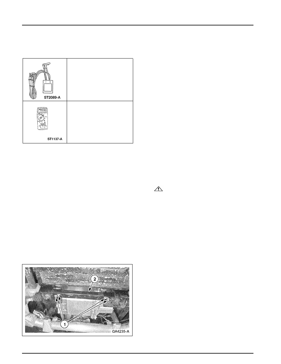
4. Remove the cross bar.

1 Remove the bolts.
2 Remove the cross bar.

100-05-10

100-05-10

Standard Service Procedures

GENERAL PROCEDURES (Continued)

5. Disconnect the two-pin high-voltage connector.

1 Remove the retaining pin.
2 Lift up on the connector latch.
3 Pull the connector out.

6. Remove the traction inverter module (TIM)

cover plate.

Remove the 12 screws.

7. Connect the Capacitor Discharge Tool to the

Digital Multimeter.

Set the multimeter for DC volts.

100-05-11

100-05-11

Standard Service Procedures

GENERAL PROCEDURES (Continued)

8.

WARNING: Verify that the voltage is

checked across the correct terminals. Wear
the rubber insulating gloves. Failure to
correctly discharge the capacitors could
result in severe personal injury or death. 
NOTE: 
The positive and negative posts are
color coded. The positive cable has a red sleeve
on the end, and the negative cable has a black
sleeve on the end. 
Probe the positive and negative terminals of the
TIM with the leads from the Capacitor
Discharge Tool. The voltmeter will display any
voltage present. Continue to probe the terminals
until the voltmeter reads 0 volts

9. Probe the positive terminal and the case of the

TIM using the leads from the Capacitor
Discharge Tool. The voltmeter will display any
voltage present. Continue to probe the terminal
and case until the voltmeter reads 0 volts

10. Probe the negative terminal and the case of the

TIM using the lead s from the Capacitor
Discharge Tool. The voltmeter will display any
voltage present. Continue to probe the terminal
and case until the voltmeter reads 0 volts. The
TIM  capacitors have now been completely
discharged.

100-06-1

100-06-1

Pre-Delivery Instructions

Manual Table of Contents

SECTION 100-06 Pre-Delivery Instructions

VEHICLE APPLICATION:

Ranger EV

CONTENTS

PAGE

DESCRIPTION AND OPERATION

Pre-Delivery Form..................................................................................... 100-06-2


Content   ..  4  5  6  7   ..