Ford Fiesta (2011 year). Manual - part 76
 

  Index      Ford     Ford Fiesta - service repair manual 2011 year


Search            


Content   ..  74  75  76  77   ..


Ford Fiesta (2011 year). Manual - part 76


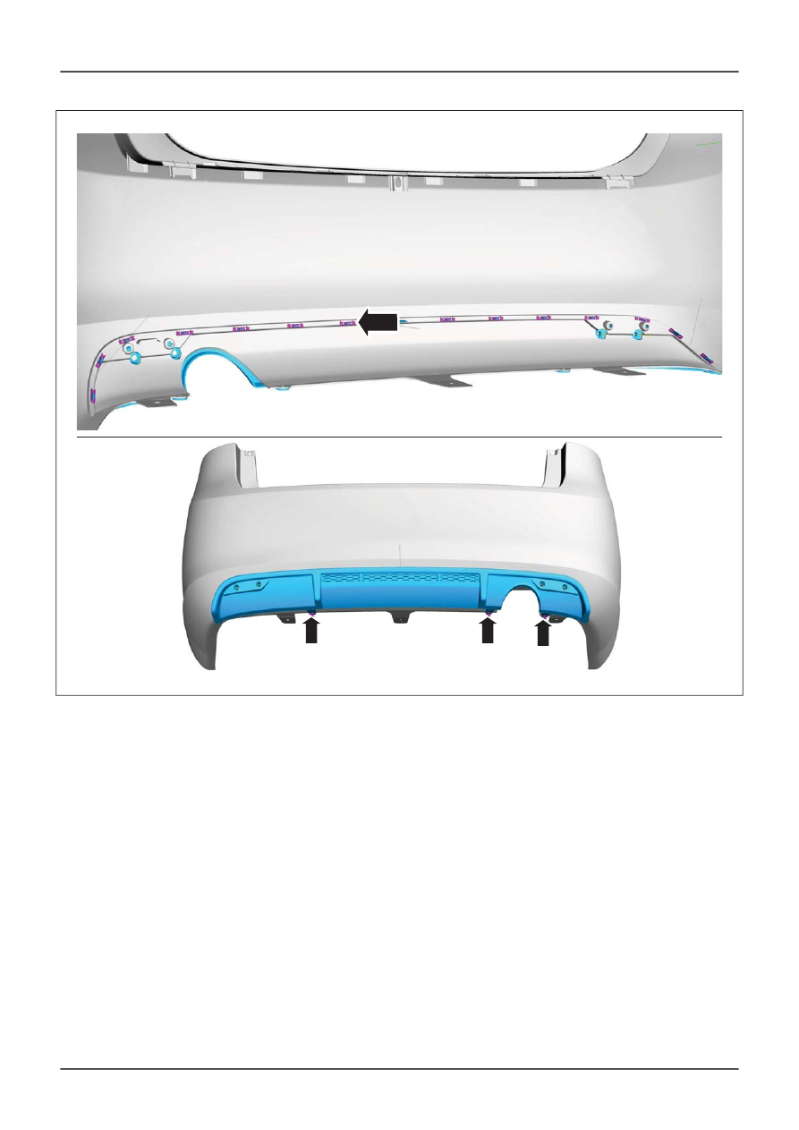
E112047

x14

Vehicles with parking aid

Parking Aid, Removal and Installation).

Installation

1. To install, reverse the removal procedure.

G1091220en

501-19-

17

Bumpers

501-19-

17

REMOVAL AND INSTALLATION

11.

Refer to: Rear Parking Aid Sensor (413-13

201

SECTION 501-20A Safety Belt System

PAGE

CONTENTS

DESCRIPTION AND OPERATION

501-20A-2

Safety Belt System (Overview)...........................................................................................

501-20A-2

Overview.............................................................................................................................

DIAGNOSIS AND TESTING

501-20A-3

Safety Belt System.............................................................................................................

501-20A-3

Principles of Operation ......................................................................................................

501-20A-3

Inspection and Verification .................................................................................................

501-20A-4

Component Test ................................................................................................................

REMOVAL AND INSTALLATION

501-20A-6

Front Safety Belt Retractor and Pretensioner.....................................................................

501-20A-7

Front Safety Belt Buckle.....................................................................................................

501-20A-8

Rear Safety Belt Retractor..................................................................................................

501-20A-10

Rear Safety Belt Buckle......................................................................................................

501-20A-11

Rear Center Safety Belt......................................................................................................

501-20A-12

Rear Center Safety Belt Buckle..........................................................................................

501-20A-

1

Safety Belt System

501-20A-

1

.

VEHICLE APPLICATION:

Safety Belt System – Overview

Overview

E102017

1

1

Description

Item

Retractor - front seat belt and belt
tensioner

Refer to: Air Bag and Safety Belt

Pretensioner Supplemental Restraint

Restraint System, Description and

Operation).

1

G1063173en

501-20A-

2

Safety Belt System

501-20A-

2

DESCRIPTION AND OPERATION

System (SRS)

(501-20 Supplemental

201

Safety Belt System

General Equipment

Ford diagnostic equipment

Principles of Operation

WARNING: All safety belt components
including retractors, buckles, front safety
belt buckle support assemblies (slider bar),
child safety seat tether brackets and
attaching hardware in use during a
collision must be removed and new
components installed. New safety belt
components should also be installed where
safety belts not in use during a collision,
are inspected and found to be damaged or
operate incorrectly. Failure to follow these
instructions may result in personal injury.

Vehicles equipped with the supplemental restraint
system (SRS) are equipped with a driver and
passenger safety belt retractor(s) and pretensioner.
The safety belt pretensioners are controlled as part
of the SRS.

REFER to: Air Bag and Safety Belt Pretensioner

Supplemental Restraint System, Description and
Operation).

The rear seat safety belt buckles are mounted
directly to the floor pan underneath the rear seat
cushion. When the ignition is turned on the RUN
position the SRS warning indicator will illuminate
for three seconds. If the SRS, including the safety
belt electrical system, is operating correctly the
SRS warning indicator will be extinguished. If a
fault is detected the SRS warning indicator will

generate a lamp fault code.

REFER to: Air Bag and Safety Belt Pretensioner

Supplemental Restraint System, Description and

Operation).

The safety belt retractor, mounted within the base
of the B-pillar, incorporates a torsion bar load
limiting device. The device consists of a retractor
reel which is mounted onto a spindle (torsion bar)
which, once the sensor has locked the retractor
reel and predetermined load is applied, twists and
pays out additional webbing into the system. The
deceleration force required to initiate this sequence
is approximately the same as that required to
initiate air bag deployment. The torsion bar load
limiting device will only react if the safety belt is in
use at the time of impact.

Rear seat safety belt retractors do not use this type
of retractor, they are equipped with a conventional
retractor.

Emergency Locking Retractor

The retractors in all seat positions feature
emergency locking retractor(s). The emergency
locking retractor is part of the safety belt system
that in normal operation allows free movement of
the belted occupant. In an emergency the
emergency locking retractor will lock, preventing
webbing payout and hence forward movement of
the occupant. Locking may be achieved by one of
two mechanisms:

Vehicle Motion Sensor

vehicle motion sensor is operated by sudden
deceleration of the vehicle or excessive tilt. Once
operated the vehicle motion sensor causes a
locking pawl to be engaged, thus locking the
retractor, preventing webbing payout. When the
vehicle is stationary, the vehicle motion sensor
stabilizes, causing the pawl to disengage and

unlock

the retractor, allowing webbing payout.

Webbing

Motion Sensor

The

emergency locking retractor webbing motion

sensor is operated by rapid acceleration of the
webbing. Once operated, it causes a locking pawl
to be engaged thus locking the retractor. Webbing
payout is prevented in the same manner as vehicle
motion sensor.

Inspection and Verification

1. Verify the customer concern.

2. Visually inspect for obvious signs of mechanical

and electrical damage.

Visual Inspection Chart

Mechanical

• Safety belt retractor

• Safety belt buckle

• Safety belt retractor and pretensioner

3. If an obvious cause for an observed or reported

concern is found, correct the cause (if possible)
before proceeding to the next stop.

4. If the cause is not visually evident, verify the

G1055906en

501-20A-

3

Safety Belt System

501-20A-

3

DIAGNOSIS AND TESTING

Supplemental Restraint System (SRS)

(501-20

Supplemental Restraint System (SRS)

(501-20

symptom and

refer to the Symptom Chart.

201


Content   ..  74  75  76  77   ..