Ford Falcon. Manual - part 306
 

  Index      Ford     Ford Falcon - service repair manual 2002-2005 year


Search            


Content   ..  304  305  306  307   ..


Ford Falcon. Manual - part 306


412-02-28 Heating 

and 

Ventilation 412-02-28

REMOVAL AND INSTALLATION (Continued)

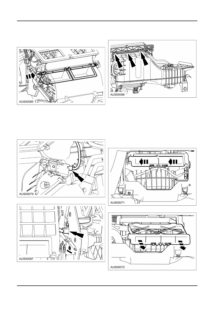
5.  Maintain force on airmix shaft end and ensure

4.  Unclip Harness and remove.

airmix door is depressed fully as shown in sketch

thus correctly aligning airmix door to shaft.

Installation
1.  Refit components in reverse order.

Dual Zone Sub Harness

Filter and Cover Assembly — Mesh

Removal

(Standard Fitment)

1.  Refer to HVAC Assembly removal procedure in

Removal

this section and follow steps 1 - 12 inclusive.

1.  Refer to glove compartment removal procedure,

2.  Disconnect harness connector from

Section 501-12 to gain access to Filter.

Actuator-Electric Airmix.

2.  Slide Mesh Filter and Cover assembly to open

position (LH side).

3.  Disconnect harness connector from HIM.

3.  Pull out Filter-assembly.

Installation
1.  Refit components in reverse order.

G34257 en

412-02-29 Heating 

and 

Ventilation 412-02-29

REMOVAL AND INSTALLATION (Continued)

Filter — Particle (Optional Fitment)

Vent Outlet Register — Outboard

Register

Removal
1.  Refer glove compartment removal procedure,

Removal and Installation

Section 501-12 to gain access to Filter.

1.  Peel off door seal over area covering end cap of

2.  Slide Cover and Seal Assembly to open (LH side).

instrument panel.

2. Remove 

end 

cap.

3.  Remove Cover & Seal Assembly.

3.  Remove trim spear from instrument panel. Care

must be taken with trim removal or inboard

retainer clip will be broken.

4.  Pull out Particle Filter.

4.  Remove three screws/self tappers from registers.

Ease register on inboard top edge to dislodge clip

and remove register.

Installation
1.  Refit components in reverse order.

5.  Assemble in reverse order.

G73255 en

412-02-30 Heating 

and 

Ventilation 412-02-30

REMOVAL AND INSTALLATION (Continued)

Vent Outlet Register — Centre

Installation

Register

1. Position 

Air 

Register.

Removal
1.  Remove Interior Command Centre and Remote

Key Receiver taking all precautions described in

section 413-08.

2.  Remove wire harness from Air Register.

2.  Tighten 3 X M5 screws to 1.5 Nm, top centre

screw first.

3.  Remove 3 X M5 screws from Air Register.

3.  Reposition wire harness to Air Register.

4. Remove 

Air 

Register.

4.  Install the Remote Key Receiver and the ICC.

Refer to Section 413-08.

Vent Outlet Register — Floor Console

Register

Removal and Installation
1.  Close flaps on register.

G73255 en

412-02-31 Heating 

and 

Ventilation 412-02-31

REMOVAL AND INSTALLATION (Continued)

2.  Pry register out of lower retainer clips first, then

4.  Invert console and ease rear section away from

top clips.

main body.

3.  Remove register.

5.  Remove eight retaining screws locating duct to

console.

4.  On assembly of register, enter lower clips first and

roll register into place.

Floor Console Duct

Removal and Installation

The floor console duct is removed from the vehicle as

part of the floor console assembly. The duct can then

be separated form the console.
1.  Remove floor console and duct assembly (Refer

to section 501-12).

2.  Remove vent outlet floor console register (Refer

to procedure in this section).

3.  Lift console lid and remove two rearmost screws.

6.  Carefully spread console at front to allow duct

clearance over locating lugs. Spread rear of

console at rear and lift out duct.

7.  To install, reverse the steps 1-6.

G73262 en


Content   ..  304  305  306  307   ..