Ford Falcon. Manual - part 292
310-00-9 Fuel
System 310-00-9
GENERAL PROCEDURES
2. Start the engine if possible and note the fuel
Pump Operation Check
pressure at idle.
1. Detach the fuel delivery line (the line coming from
If the engine cannot be started install a remote
the filter) from the fuel rail. Place the end of the
control switch at the relay.
delivery line in a container.
Operate the switch and note pressure.
Specification:
2. Switch ignition on. The pump should deliver fuel
for one second. Switch ignition off.
270 kPa Base I6
3. If the pump does not run, detach the wiring
300 kPa Base V8
connector from the pump end of the loom. On
400 kPa Turbo I6
sedan this connector is located beneath the
3. If the pressure reading is low slowly close off the
plastic cover which is under the rear seat cushion.
fuel delivery test line between the gauge and the
On wagon the connector is accessible via a
fuel rail while operating the pump. Pressure
rubber grommet in the floor of the luggage space.
should increase to at least 400 kPa.
On utes the connector may be accessible under
If pressure does not increase a faulty fuel pump is
the vehicle via the extended wiring loom.
indicated.
4. Connect a voltmeter across the loom terminals.
Switch on the ignition while observing the meter.
Fuel Flow (Volume) Test
The meter should read battery voltage for
approximately one second then drop to zero.
WARNING: Engine must be switched off
Failure to do this indicates a fault in the power
during this test.
supply circuit.
1. Disconnect the fuel return line from the steel line
5. Check the pump for continuity. Connect an
(lower dash panel) and place the end of the
ohmmeter across the terminals of the pump lead.
flexible hose into a graduated container.
(Specifications - less than 10 ohms.)
2. Operate the remote control switch for 10 seconds.
NOTE: Do not attempt to detach the fuel pump
lead from the pump bracket.
3. Remove the measuring container and check
contents against specification:277 cc.
Pressure Test
NOTE: Fuel volume must be at nominal regulated
pressure. See specifications listed in Pressure
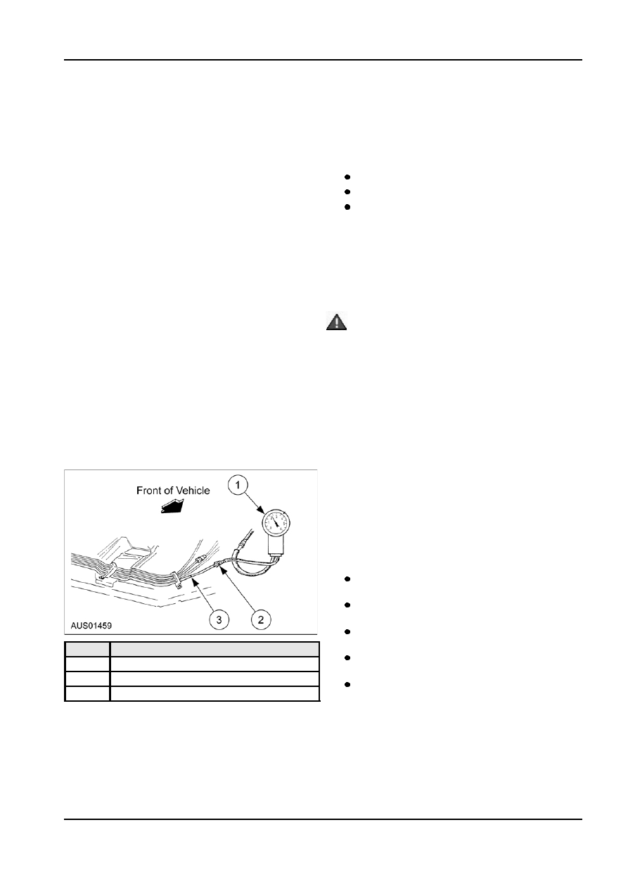
1. ’T’ The fuel pressure gauge (refer Special Tools
Test of General Procedures in this chapter.
section) into the fuel delivery line.
Fuel System Pressure Retention
1. Operate the remote control switch for 10 seconds
and note fuel pressure.
Maximum pressure drop permissible is 10% in 10
seconds. A pressure drop in excess of this figure
indicates a leak in the pressure system.
2. Check by closing off the pressure line just before
the gauge.
No pressure drop - leak in pressure line to
pump or in non-return valve of pump.
Pressure continues to drop - leak in injectors,
pressure regulator or fuel rail connections.
To determine source of pressure leak close
off the fuel return line.
Item
Description
No pressure drop - replace pressure
1
Fuel Pressure Gauge
regulator.
2
Quick Connect Fitting
Pressure continues to drop - check fuel rail
3
Pressure Line
connections and test injectors.
3. Remove the pressure gauge and reconnect fuel
lines.
4. Check for fuel leaks.
5. Remove the remote control switch and install the
loom plug in the base of the relay.
G345278 en