Ford Falcon. Manual - part 284
 

  Index      Ford     Ford Falcon - service repair manual 2002-2005 year


Search            


Content   ..  282  283  284  285   ..


Ford Falcon. Manual - part 284


308-03b-50 

Manual Transmission — TR3650 

308-03b-50

ASSEMBLY (Continued)

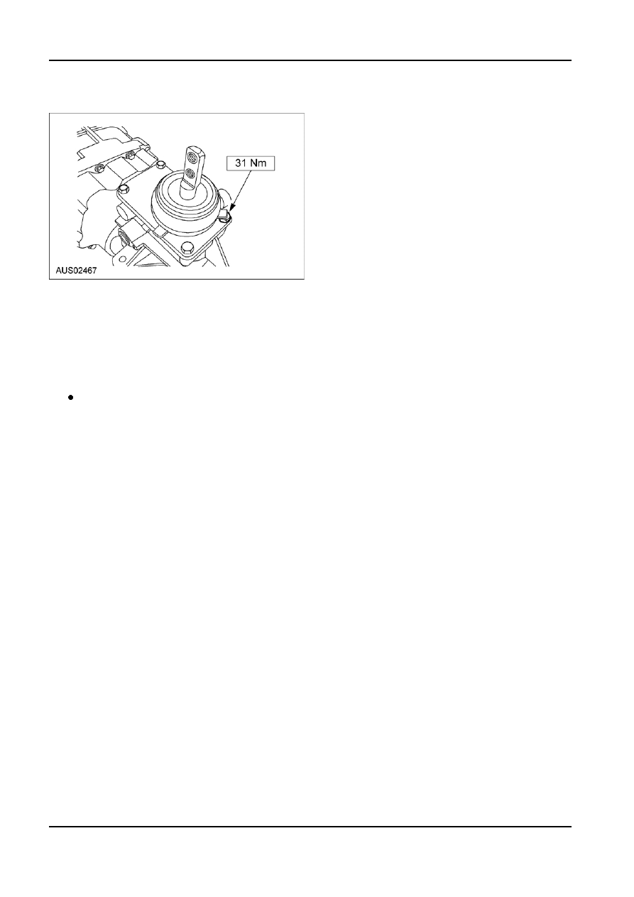
59. Install the gear shift lever.

60. Install the clutch release hub and bearing and the

clutch release lever. For additional information,

refer to Section 308-01.
NOTE: Before installing the transmission, the ball

stud, the clutch release lever and the input shaft

guide tube must be cleaned and lubricated.

61. Fill the transmission with transmission fluid to the

specified level.

Transmission capacity is 3.8 liters (8.0 pints).

G34245 en

308-03b-51 

Manual Transmission — TR3650 

308-03b-51

INSTALLATION

Transmission

NOTE: Before installing the transmission, the ball

stud, clutch release lever and the input shaft must be

cleaned and lubricated. Use Motorcraft Premium

Long-Life Grease XG-1-C or XG-1-K or equivalent

meeting Ford specification ESA-M1C75-B.

Installation
1.  To install, reverse the removal procedure. For

additional information, refer to Transmission in

this section.

Check, and as necessary, fill the transmission

with transmission fluid. The total fill capacity is

3.8L (8.0 pt).

2.  Apply sealant to the fill plug threads and install

the fill plug.

Use pipe sealant with Teflon®.

G34246 en

308-06-1 

Manual Transmission External Controls 

308-06-1

SECTION : 308-06 Manual Transmission External

Controls

VEHICLE APPLICATION : 2003.0 BA Falcon
CONTENTS  

PAGE

SPECIFICATIONS

 Specifications   ........................................................................................................................308-06-2

DIAGNOSIS AND TESTING

  External Controls   ..................................................................................................................308-06-3

  Inspection and Verification  ...................................................................................................308-06-3

 Symptom 

Chart 


....................................................................................................................308-06-3

 Pinpoint 

Tests 


......................................................................................................................308-06-3

REMOVAL AND INSTALLATION

  Gearshift Lever   .....................................................................................................................308-06-5

  Gearshift Boot and Retainer Assembly   .................................................................................308-06-5

308-06-2 

Manual Transmission External Controls 

308-06-2

SPECIFICATIONS

Torque Specifications

Description

Nm

Gearshift lever retaining nut

8.9 - 12.1

Gearshift lever retaining bolt

29.5 -40.3

Gearshift lever boot and retainer

8.9 - 12.1

assembly retainer nut

G73254 en


Content   ..  282  283  284  285   ..