Ford Falcon. Manual - part 271
 

  Index      Ford     Ford Falcon - service repair manual 2002-2005 year


Search            


Content   ..  269  270  271  272   ..


Ford Falcon. Manual - part 271


308-03a-46 

Manual Transmission — I6 

308-03a-46

ASSEMBLY (Continued)

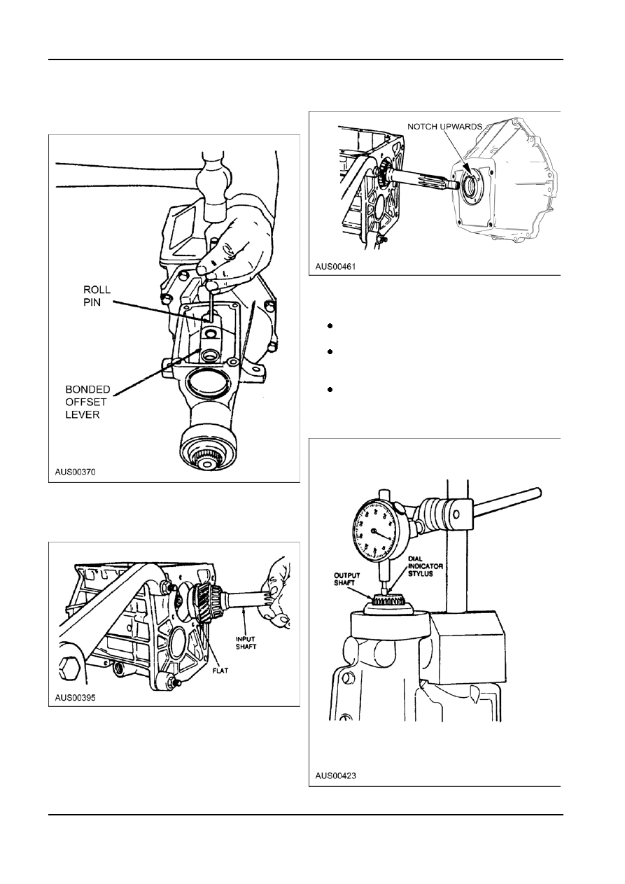
29. Using a suitable pin punch, align the hole in

33. Tighten retaining bolts to 15-27 Nm (11-20 lb-ft).

shifter shaft with hole in bonded offset lever and

install roll pin.

34. Remount the transmission (with flywheel housing)

in the holding fixture and check output shaft

geartrain end play as follows:

Rotate transmission to the vertical position

with extension housing facing up.
Mount Dial Indicator with Bracketry on the

extension housing with the indicator stylus

contacting the output shaft.
Rotate the input and output shafts. Zero the

dial indicator.
NOTE: Output shaft geartrain end play must

be checked and adjusted at this point.

30. Install input shaft. Align flat on sychronizer teeth

with countershaft before installing input shaft.
NOTE: Ensure 3-4 synchronizer blocking ring is

still in proper position.

31. Install bearing race in the bearing retainer located

in the back of the flywheel housing.
NOTE: Do not install end play shims at this point.

32. Temporarily, attach the flywheel housing to the

transmission main case.

G34528 en

308-03a-47 

Manual Transmission — I6 

308-03a-47

ASSEMBLY (Continued)

Using a wood block, push upward on the

37. Reattach the flywheel housing (with shims and

input shaft and note the dial indicator reading.

bearing race located in the integral bearing

retainer) and hand tighten the four main

NOTE: A shim must be installed that is the

case-to-flywheel housing bolts. Tighten the four

thickness of the dial indicator reading. This

integral flywheel housing-to-main case retaining

will provide zero end play.

bolts to specification.

A pre-load of 0.01-0.1mm must be applied.

38. Torque the four integral flywheel housing-to-main

case retaining bolts  to specification. Check

 CAUTION: Thickest shim must be installed

end play.

closest to the front bearing cup.
35. Detach the transmission from the holding fixture

and remove the flywheel housing. Remove

bearing race from flywheel housing and install the

necessary shim(s).

39. Apply a 3.2mm (1/8-inch) bead of Silicone Sealer

RTV Silastic 1080 or equivalent on the turret

cover.

36. Apply a 3.2mm (1/8 inch) bead of Silicon Sealer

RTV Silastic 1080 or equivalent to the edge of the

integral bearing retainer and around the retainer

bolt holes in the back of the flywheel housing.

G34528 en

308-03a-48 

Manual Transmission — I6 

308-03a-48

ASSEMBLY (Continued)

40. Position turret cover on the extension housing and

tighten the retaining bolts to 24-30 Nm.

41. Install and tighten drain plug to 27-40 Nm.

G34528 en

308-03b-1 

Manual Transmission — TR3650 

308-03b-1

SECTION : 308-03b Manual Transmission —

TR3650

VEHICLE APPLICATION : 2003.0 BA Falcon
CONTENTS  

PAGE

SPECIFICATIONS

 Specifications   ......................................................................................................................308-03b-2

DESCRIPTION AND OPERATION

  Manual Transmission   ..........................................................................................................308-03b-3

  Transmission Identification   ...............................................................................................308-03b-7

DIAGNOSIS AND TESTING

  Manual Transmission   ..........................................................................................................308-03b-8

GENERAL PROCEDURES

  Bearings — Inspection   ........................................................................................................308-03b-9

IN-VEHICLE REPAIRS

 Seal   ...................................................................................................................................308-03b-11

  Gearshift Lever and Boot   ..................................................................................................308-03b-11

  Gearshift Boot and retainer Assembly   ..............................................................................308-03b-12

REMOVAL

 Transmission   .....................................................................................................................308-03b-13

DISASSEMBLY

 Transmission   .....................................................................................................................308-03b-15

DISASSEMBLY AND ASSEMBLY OF SUBASSEMBLIES

  Input Shaft and Bearing   ....................................................................................................308-03b-24

  Output Shaft   ......................................................................................................................308-03b-25

  Countershaft Bearing   ........................................................................................................308-03b-36

 Synchronizers   ...................................................................................................................308-03b-37

  Gearshift Rail Bushing   ......................................................................................................308-03b-37

  Gearshift Rail and Fork   .....................................................................................................308-03b-38

ASSEMBLY

 Transmission   .....................................................................................................................308-03b-39

INSTALLATION

 Transmission   .....................................................................................................................308-03b-51


Content   ..  269  270  271  272   ..