Ford Falcon. Manual - part 256
 

  Index      Ford     Ford Falcon - service repair manual 2002-2005 year


Search            


Content   ..  254  255  256  257   ..


Ford Falcon. Manual - part 256


308-01-11 Clutch 308-01-11

REMOVAL AND INSTALLATION (Continued)

Installation

4.  Separate the flywheel from the crankshaft.

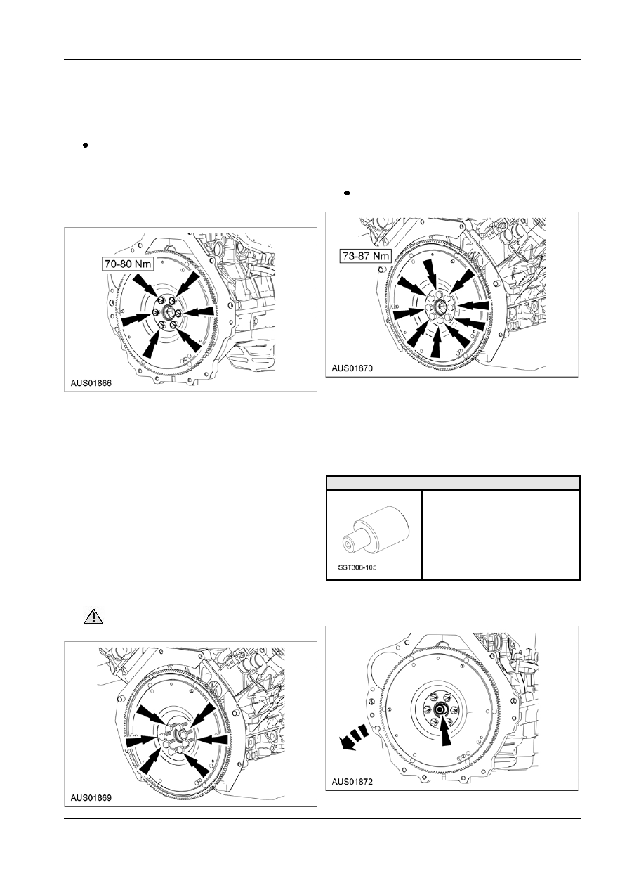
1.  Position the flywheel onto the crankshaft and

5.  Remove the bolts remaining in the crankshaft.

install the flywheel-to-crankshaft bolts.

6.  Remove the flywheel.

Apply threadlock and sealer to bolt threads.

Installation

NOTE: Both the standard I6 & XR6 Turbo

1.  Position the flywheel onto the crankshaft and

flywheel and crankshaft are designed with a

install the flywheel-to-crankshaft bolts.

single offset bolthole to ensure correct

Apply the threadlock and sealer to bolt

angular alignment between crankshaft and

threads.

flywheel. These holes must be aligned before

installing the six flywheel-to-crankshaft bolts.

2.  Install the disc and pressure plate. For additional

information, refer to Disc and Pressure Plate in

2.  Install the disc and pressure plate. For additional

this section.

information, refer to Disc and Pressure Plate in

3.  Install the transmission. For additional information,

this section.

refer to Section 308-03.

3.  Install the transmission. For additional information,

refer to Section 308-03.

Pilot Bearing — All Vehicles

Flywheel — All V8 Vehicles (incl XR8 &

Special Tool(s)

GT)

Installer, Pilot Bearing

Removal

308-105 (T85T-7137-A)

1.  Remove the transmission. For additional

information, refer to Section 308-03.

2.  Remove the clutch disc and pressure plate. For

additional information, refer to Disc and Pressure

Plate in this section.

3.  Remove six of the eight bolts. Leaving two

Removal

opposing bolts in place, loosely.

1.  Using a standard bearing puller, remove the

transmission input shaft pilot bearing.

 CAUTION: Two bolts should be loosened

but left in to prevent the flywheel from falling.

G86738 en

308-01-12 Clutch 308-01-12

REMOVAL AND INSTALLATION (Continued)

2.  Inspect the transmission input shaft pilot bearing

for:

misalignment and looseness in the flywheel.
needle rollers for scoring, worn or broken

needle rollers, inadequate grease or

discoloration.
seal leakage.

Installation
NOTE: 
The transmission input shaft pilot bearing

should only be installed with the seal facing the

transmission. The transmission input shaft pilot

bearing is pregreased and does not require additional

lubrication. A new transmission input shaft pilot

bearing must be installed whenever it is removed.

1.  Using a soft-face hammer and the special tool,

install the transmission input shaft pilot bearing.

G86738 en

308-01-13 Clutch 308-01-13

DISASSEMBLY AND ASSEMBLY

Flywheel Auto Flex-Plate (XR6 Turbo

Ring Gear — All Vehicles except XR6

only)

Turbo

Disassembly

Vehicle Item

Specification

QTY

variant

XR6T Bolt -

V810171S26D

4

M10x1.25x17

HEX HD

Disassembly
1.  Remove the flywheel assembly. For additional

information, refer to Flywheel section.

2.  Index mark the flywheel disc together with the

auto-flex plate.

3.  Undo the four screws attaching the flywheel disc

to the auto flex-plate and separate the two

components.

Assembly

1.  Using a brass drift and hammer, drive the flywheel

ring gear off the flywheel.

1.  Position the flywheel disc on the auto flex plate

and align the markings on the disc and flex plate.

 CAUTION: Do not heat the flywheel ring

NOTE: Both the XR6 Turbo flywheel and

gear to remove.

crankshaft are designed with a single offset

bolthole to ensure correct angular alignment

 CAUTION: Tap the flywheel ring gear

between the crankshaft and flywheel. These holes

evenly to prevent binding.

must be aligned before installing the six

flywheel-to-crankshaft bolts.

Assembly

 WARNING: This procedure should be

performed only by a correctly equipped and

experienced acetylene torch operator. To avoid

personal injury, use tongs or wear welding gloves

and safety goggles when handling the heated

flywheel ring gear.
1.  Evenly heat the flywheel ring gear.

 CAUTION: Do not heat the flywheel ring

gear beyond 278

°C (500°F). Use heat

indicating crayons to prevent over heating.

 CAUTION: Keep the torch moving to

prevent hot spots.

2.  Install the flywheel disc-to-flex plate bolts.

G86740 en

308-01-14 Clutch 308-01-14

DISASSEMBLY AND ASSEMBLY (Continued)

2.  Install the flywheel ring gear using a brass drift.

NOTE: The bevel on the flywheel ring gear must

face the rear of the flywheel.

Ring Gear — XR6 Turbo only

 WARNING: The ring gear should not be

removed from the auto flex plate on XR6T flywheel

assembly. Replace as assembly is required.

G86740 en


Content   ..  254  255  256  257   ..