Ford Falcon. Manual - part 227
307-01-11 Automatic
Transmission 307-01-11
DESCRIPTION AND OPERATION (Continued)
Engine Speed
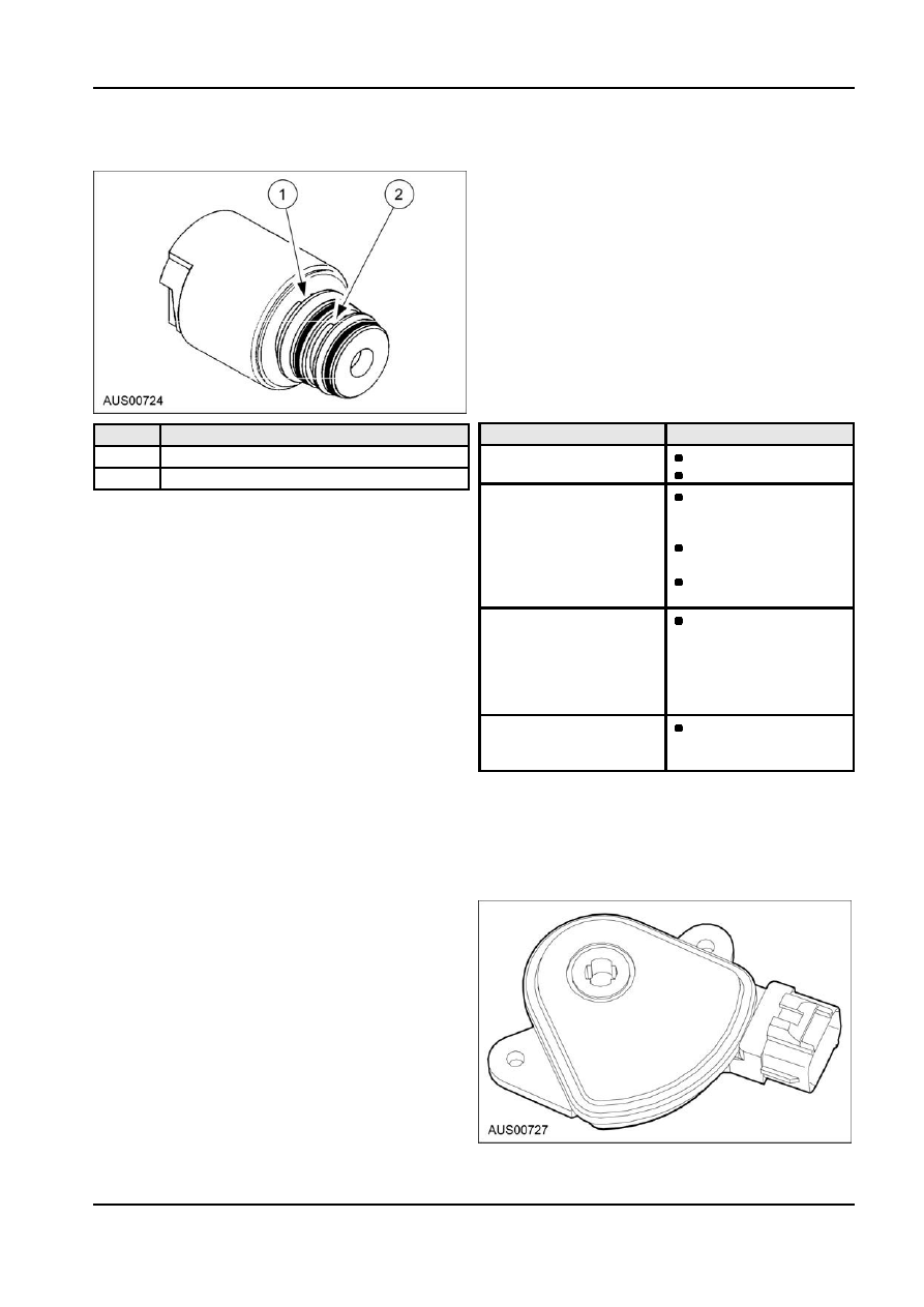
Solenoids
The engine speed signal is taken from the tachometer
signal line.
Road Speed
The road speed signal is taken from the speedometer
transducer to speedometer line (ABS model only). On
non-ABS models, the speed signal is taken from the
speedometer transducer on the output shaft.
Transmission Sump Temperature
This sensor takes the form of a thermistor located in
the solenoid wiring loom within the transmission.
Above certain temperatures, overheat strategies are
invoked as indicated in the table below.
Temp (
°C)
Overheat Strategy
Item
Description
115
Fan engaged.
1
Exhaust
No driver alert.
2
Line 500
120
In Adaptive mode,
Solenoids Nos. 1 to 6 are mounted in the valve body.
power shift schedule
Solenoid No. 7 is mounted in the pump cover.
is selected.
Solenoids 1 and 2 are normally open ON/OFF
Engine temperature
solenoids that combine with other solenoids to set the
jewel will appear.
selected gear.
PRNDL indicator will
Solenoids 3 and 4 are normally open ON/OFF
flash.
solenoids that combine to control shift quality
125
Torque converter
sequencing. They also combine with other solenoids
lock-up invoked in
to obtain certain gear states.
2nd, 3rd and 4th
Solenoid 5 is a variable pressure solenoid (VPS) that
gears above certain
ramps the pressure during gear changes to control
calibratable shaft
shift quality. It is also used to obtain certain gear
speed points.
states in combination with other solenoids.
135
Vehicle restricted to a
Solenoid 6 is a normally open ON/OFF solenoid that
calibratable constant
sets the high/low level of line pressure.
torque.
Solenoid 7 is a normally open ON/OFF solenoid that
Transmission Range Sensor
controls the application of the converter clutch.
The transmission range TR sensor is incorporated in
Accelerator Pedal Position (APP) Sensor
the inhibitor switch mounted on the side of the
The APP is part of the Electronic Throttle Control ETC transmission case and provides discrete resistance
system. ETC provides direct throttle control by
values indicating the gear selected by the gear shift
eliminating the throttle cable. A spring is contained in
lever.
the APP to proved pedal resistance. The APP
contains three potentiometers: one reverse slope full
ratio, one forward slope full-ratio and one forward
slope half-ratio. This allows an accurate picture of
both the accelerator pedal position and rate of change
to be sent to the PCM, while providing a failsafe
backup if one of the potentiometers fails. The APP is
not serviceable, if faulty replace the APP as an
assembly.
G73081 en