Ford Falcon. Manual - part 222
 

  Index      Ford     Ford Falcon - service repair manual 2002-2005 year


Search            


Content   ..  220  221  222  223   ..


Ford Falcon. Manual - part 222


303-14-102 

Powertrain Control Management 

303-14-102

GENERAL PROCEDURES (Continued)

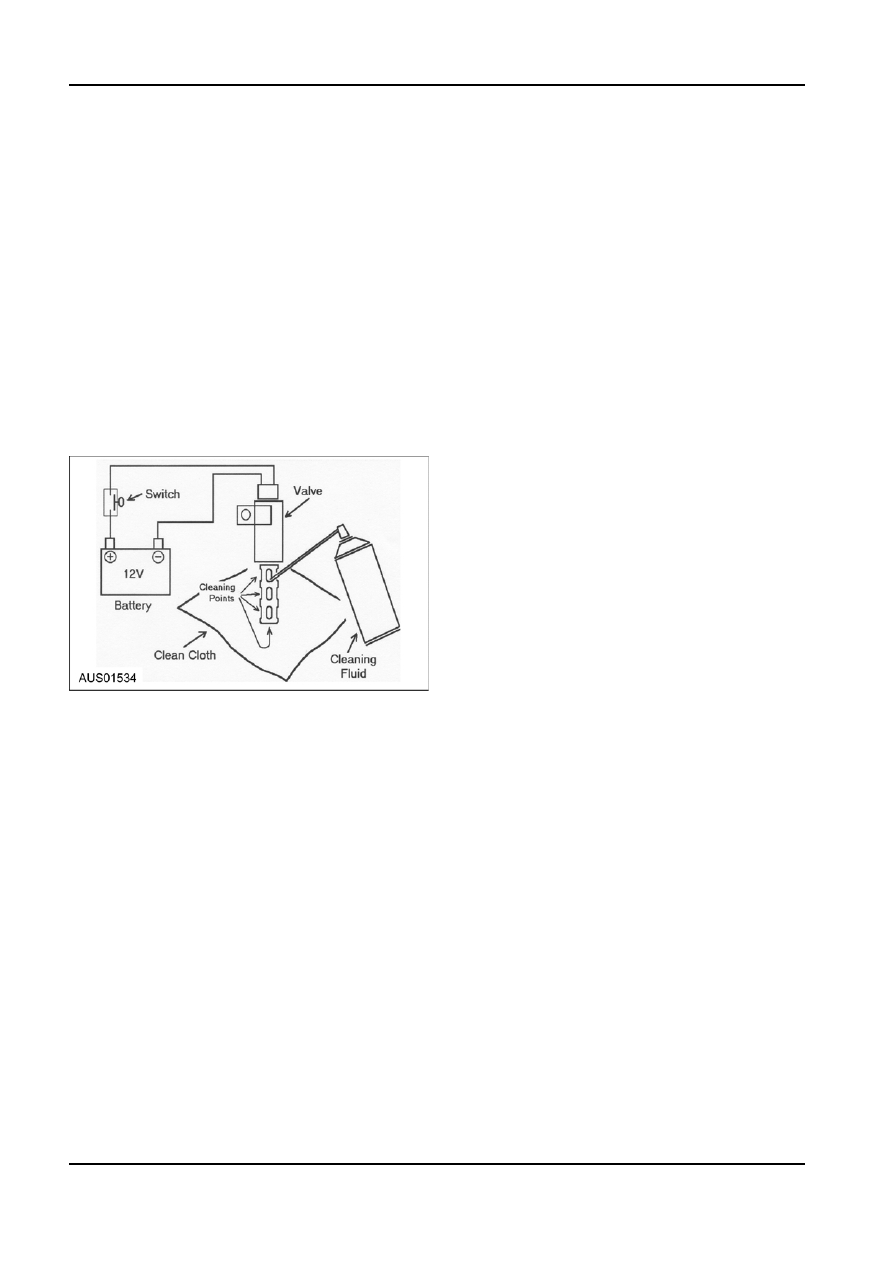
4. 12V 

Vehicle 

Battery.

5. Safety 

Glasses.

Procedure.
1.  Remove jammed Oil Control Valve (OCV) Ref.

Engine Section 303-01a, b & c.

2.  Place valve on a clean cloth.
3.  Connect 12V onto valve through a push button

momentary switch.

4.  Hold valve upright on clean cloth.
5.  Spray cleaning Fluid into ports of valve while

pressing momentary switch 3 - 4 times per

second.

6.  Clean down the center of the valve using a similar

process.

7.  Repeat process until the obstruction is removed.
8.  Re-fit valve and test.

G98141 en

303-14-103 

Powertrain Control Management 

303-14-103

REMOVAL AND INSTALLATION

Camshaft Position Sensor (I6 Engine)

Crankshaft Position (CKP) Sensor (I6

Engine)

Removal
1.  Remove the camshaft position (CMP) sensor.

Removal


1.  Disconnect the electrical connector

1.  Remove the crankshaft position (CKP) sensor.


2.  Remove the retaining bolt


1.  Disconnect the electrical connector


3.  Remove the sensor


2.  Remove the retaining bolt


3.  Remove the sensor

Installation
1.  To Install, reverse the removal procedure.

NOTE: Be sure the sensor wiring is routed away from

the battery cable.

Camshaft Position Sensor (V8 Engine)

Installation

Removal

1.  To Install, reverse the removal procedure.

1.  Disconnect the battery ground cable. For

Crankshaft Position (CKP) Sensor (V8

additional information, refer to Section 414-01.

Engine)

2.  Disconnect the camshaft position (CID) sensor

electrical connector.

Removal

3.  Unscrew the retaining bolt and remove the CID

1.  Remove the A/C compressor. For additional

sensor.

information, refer to Section 412-03.

2.  Remove the crankshaft position (CKP) sensor.
 

1.  Disconnect the electrical connector

 2. 

Remove 

the 

bolt


3.  Remove the sensor

Installation
1.  To Install, reverse the removal procedure.

Knock Sensor (I6 Engine)

Removal

Installation

1.  Disconnect the knock sensor (KS) electrical

1.  To Install, reverse the removal procedure.

connector.

G98143 en

303-14-104 

Powertrain Control Management 

303-14-104

REMOVAL AND INSTALLATION (Continued)

2.  Remove the bolt and the KS.

4.  Remove the CHT sensor.

Installation

Installation

1.  To Install, reverse the removal procedure.

1.  To Install, reverse the removal procedure.

Cylinder Head Temperature (CHT)

Throttle Position (TP) Sensor (I6, LPG

Sensor (I6 Engine)

& Turbo Engines)

Removal

Removal

1.  Disconnect the cylinder head temperature (CHT)

1.  Ensure the ignition has been switched off and the

sensor electrical connector.

battery disconnected. For additional information,

refer to Section 414-01.

2.  Using a ring spanner, remove the CHT sensor.

2.  Remove the inlet duct from the throttle body.
3.  Remove the TP sensor.
 

1.  Disconnect the electrical connector from the

TP sensor by sliding the red locking tab out

and pressing the clip release.


2.  Remove the 2 TP sensor retaining bolts.


3.  Remove the TP sensor from the throttle body.

I6 & Turbo

Installation
1.  To Install, reverse the removal procedure.

Cylinder Head Temperature (CHT)

Sensor (V8 Engine)

Removal
1.  Disconnect the battery ground cable. For

additional information, refer to Section 414-01.

2.  Disconnect the electrical connector and remove

the alternator.

3.  Disconnect the CHT sensor electrical connector.

G98143 en

303-14-105 

Powertrain Control Management 

303-14-105

REMOVAL AND INSTALLATION (Continued)

7.  Remove the throttle TP sensor.

LPG Engine


1.  Remove the 2 TP sensor retaining bolts.


2.  Remove the TP sensor from the throttle body.

Installation
1.  Fit the new bolts provided with the new TP sensor

and tighten them to 2 - 4Nm.

Installation

2.  Reconnect the electrical connector ensuring there 1.  Fit the new TP sensor to the throttle body,

is a positive “click” as the safety clip engages.

ensuring that the locating pin on the TP sensor

3.  Slide the red locking tab into position.

aligns with the hole in the throttle body.

4.  Refit the inlet duct to the throttle body.

2.  Fit the new bolts provided with the new TP sensor

and tighten them to 2 - 4Nm.

5.  Reconnect the battery.

3.  Refit the gasket and the throttle body to the inlet

6.  Switch on the ignition then fully depress the

manifold and tighten the bolts to 8 -12Nm.

accelerator pedal and release it.

4.  Reconnect both electrical connectors ensuring

7.  Perform key-on, engine-off test to ensure no TP

there is a positive “click” as the safety clips

sensor codes are present.

engage.

8.  Start the car and ensure normal operation.

5.  Slide the red locking tabs into position.

Throttle Position (TP) Sensor (V8

6.  Refit the inlet duct to the throttle body.

Engine)

7.  Reconnect the battery.
8.  Switch on the ignition then fully depress the

Removal

accelerator pedal and release it.

1.  Ensure the ignition has been switched off and the

9.  Perform key-on, engine-off test to ensure no TP

battery disconnected. For additional information,

sensor codes are present.

refer to Section 414-01.

10. Start the car and ensure normal operation.

2.  Remove the inlet duct from the throttle body.
3.  Disconnect the 4 way electrical connector from

Powertrain Control Module (PCM) (I6

the TP sensor by sliding the red locking tab out

Engine)

and pressing the clip release.

4.  Disconnect the 2 way electrical connector from

The PCM is installed in the engine compartment on

the throttle body motor by sliding the red locking

the bracket over the front nearside strut tower. Three

tab and pressing the clip release.

security bolts secure the PCM to the PCM bracket.

5.  Remove the 4 bolts retaining the throttle body to

Removal

the inlet manifold.

1.  Ensure the ignition has been switched off and the

6.  Note the throttle body orientation, then remove

battery disconnected. For additional information,

the throttle body, being careful with the gasket.

refer to Section 414-01.

2.  Use a small high-speed grinding tool with a small

circular grinding disc to cut slots on the 3 security

bolts holding the PCM to the bracket.

 CAUTION: This operation produces

sparks and debris that can cause fire and

personal injury.

Perform this operation in a well-ventilated

area.

G98151 en


Content   ..  220  221  222  223   ..