Ford Falcon. Manual - part 199
303-14-10
Powertrain Control Management
303-14-10
DESCRIPTION AND OPERATION (Continued)
Fuel Pressure Regulator
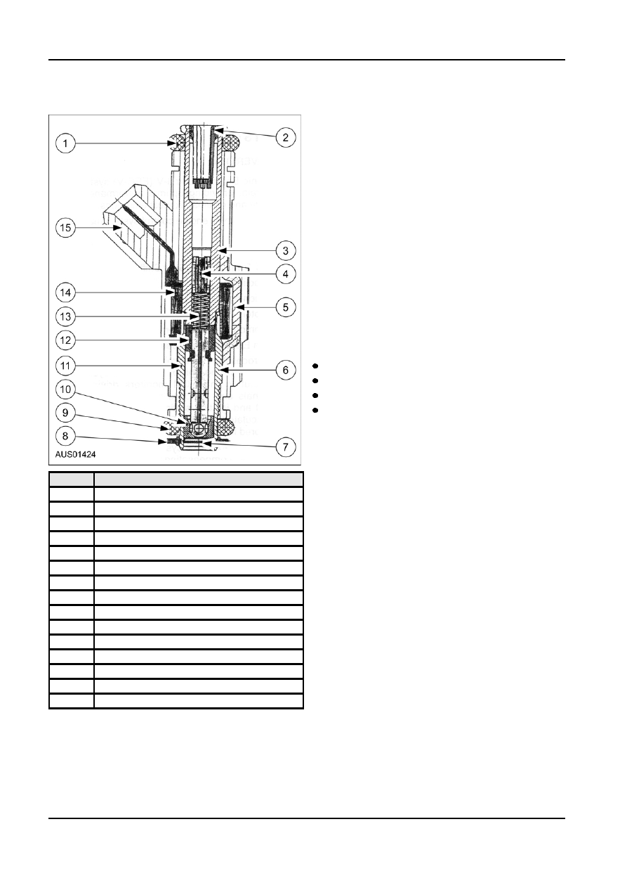
Fuel Injector
The fuel pressure regulator is attached to the outlet
side of the fuel rail and controls the pressure within
the fuel rail. Fuel is delivered to each injector at the
same pressure to ensure the volume of fuel injected is
equal for each cylinder.
The regulator is a diaphragm-operated relief valve.
One side of the diaphragm senses fuel pressure, and
the other side is connected to the intake manifold
vacuum. Fuel pressure is established by a spring
pre-loading applied to the diaphragm. Balancing one
side of the diaphragm with manifold vacuum
maintains a constant pressure across the fuel
injectors. Excess fuel is bypassed through the
regulator and returned to the fuel tank. Fuel pressure
is high when engine vacuum is low.
Intake Air System
The intake air system provides clean air to the engine,
optimises airflow and is designed to minimise
induction noise. The intake air system consists of:
Air Cleaner Assembly
Inlet Ducting
Electronic Throttle Body
Inlet Manifold
Air Cleaner Assembly
The air cleaner assembly is an essential component
of the intake air system. The air cleaner assembly
houses a disposable air filter element that removes
Item
Description
dust from the intake air. The air cleaner element must
be periodically replaced according to the maintenance
1
O-ring
schedule.
2
Filter
3
Adjusting Sleeve
Air Mass Measurement System
4
Weld
The I6 and V8 engines use the “speed density” fuel
5
Shells (2 of)
injection system. In this system, the PCM has stored
in its memory the theoretical mass of intake air that
6
Weld
will be drawn into the engine at any given speed of
7
Weld
operation. Using the engine speed sensor (Crankshaft
8
Support Ring
Position CKP) signal, the Intake Air Temperature and
Manifold Absolute Pressure sensor (T-MAP), the PCM
9
O-ring
can compute the intake air mass, and from it the fuel
10
Seat & Spray Plate Assy.
required to be injected into the engine for combustion.
11
Tube Assy.
This amount of fuel injected is further corrected by
12
Needle, Ball & Armature Assy.
feedback information obtained from the Heated
Oxygen Sensor (HEGO) sensor, providing close loop
13
Spring
control of fuel injection. A further feature of this
14
Coil & Bobbin Assy.
system is the ability to ‘re-calibrate’ itself for changes
15
Plastic Body
in fuel requirements as the engine wears and the
sensors age. This is known as adaptive strategy or
learning and is an additional function derived from
HEGO sensor information.
G98122 en