Ford Falcon. Manual - part 143
 

  Index      Ford     Ford Falcon - service repair manual 2002-2005 year


Search            


Content   ..  141  142  143  144   ..


Ford Falcon. Manual - part 143


303-01b-86 

Engine — 5.4L (3V) 

303-01b-86

ASSEMBLY (Continued)

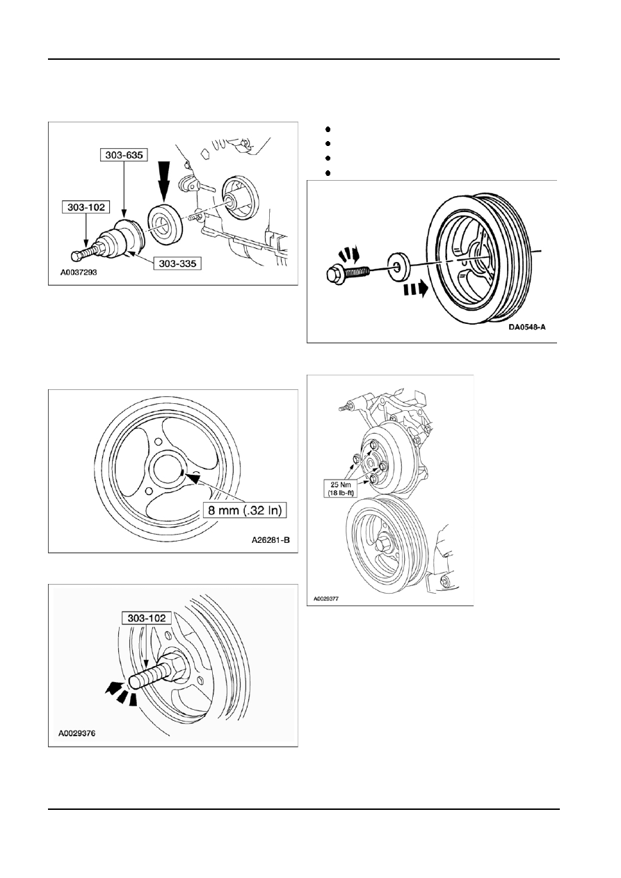
56. Use the special tools to install the crankshaft front 59. Tighten the new crankshaft pulley bolt in four

oil seal into the engine front cover.

stages.

Stage 1: Tighten to 90 Nm (66 lb-ft).
Stage 2: Loosen 360 degrees.
Stage 3: Tighten to 50 Nm (37 lb-ft).
Stage 4: Tighten an additional 90 degrees.

57. Apply silicone gasket and sealant to the Woodruff

key slot on the crankshaft pulley.
NOTE: If not secured within four minutes, the

sealant must be removed and the sealing area

cleaned. To clean the sealing area, use silicone

60. Position the coolant pump pulley on the coolant

gasket remover and metal surface prep. Follow

pump and install the bolts.

the directions on the packaging. Failure to follow

this procedure can cause future oil leakage.

58. Use the special tool to install the crankshaft

pulley.

G89799 en

303-01b-87 

Engine — 5.4L (3V) 

303-01b-87

ASSEMBLY (Continued)

61. Position the accessory drive belt tensioner and

64. Position the A/C compressor and install the bolts.

install the bolts.

65. Install the oil drain plug.

62. Install the crankshaft position (CKP) sensor and

the bolt.

66. If a new gasket is being installed, apply instant

adhesive completely around the gasket groove in

63. Position the A/C compressor bracket and install

the RH valve cover. Install the new valve cover

the bolts.

gasket.
NOTE: RH shown, LH similar.

67. Apply silicone gasket and sealant in two places

where the engine front cover meets the cylinder

head.
NOTE: RH is shown, LH is similar.
NOTE: If not secured within four minutes, the

sealant must be removed and the sealing area

cleaned. To clean the sealing area, use silicone

gasket remover and metal surface prep. Follow

the directions on the packaging. Failure to follow

this procedure can cause future oil leakage.

G89799 en

303-01b-88 

Engine — 5.4L (3V) 

303-01b-88

ASSEMBLY (Continued)

69. Position the LH valve cover and gasket on the

cylinder head and install the bolts loosely. Tighten

the bolts in the sequence shown.

68. Position the RH valve cover and gasket on the

cylinder head and install the bolts loosely. Tighten

the bolts in the sequence shown.

70. Install the eight ignition coils and bolts.

NOTE: NOTE: RH is shown, LH is similar.

G89799 en

303-01b-89 

Engine — 5.4L (3V) 

303-01b-89

ASSEMBLY (Continued)

71. Position the water bypass tube assembly and

74. Position the generator support bracket and install

install the bolts.

the bolts.

72. Install the bolt.

75. Install the intake manifold gaskets.

73. Position the generator and install the bolts.

G89799 en


Content   ..  141  142  143  144   ..