Ford Falcon. Manual - part 119
303-01a-47
Engine — I6
303-01a-47
IN-VEHICLE REPAIR (Continued)
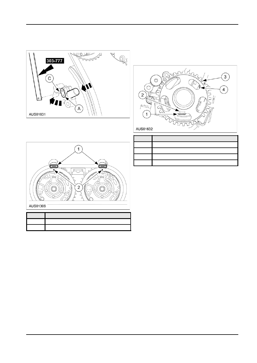
4. Push in plunger slightly so hole in A aligns with
2. Align yellow link at 6 o’clock with its position
hole C and is locked with SST.
indicator. Align orange link at 1 o’clock with the
timing indicator on tone wheel. The orange link
should be half visible within the tone wheel cut
away hole.
Installation
1. Set the crankshaft position to Top Dead Centre:
Cylinder #1 Firing (both VCT phaser timing marks
vertically upwards).
Item
Description
1
Yellow link
2
Yellow link position indicator
3
Timing indent on tone wheel
4
Orange link
3. Remove the SST 303-777 to release the
tensioner.
4. Rotate crankshaft back and forwards to check that
the slack is removed from chain.
5. Reverse removal procedure for camshaft drive
components.
Cylinder Head
Removal
Item
Description
1. Remove the radiator cooling fan assembly.
1
Yellow links
2. Remove
the
radiator.
2
Timing dot on VCT
3. Remove the valve cover. Refer to Valve Cover in
this section.
4. Remove front cover. Refer to Front Cover in this
section.
5. Remove timing chain.
6. Remove camshafts. Refer to Camshaft in this
section.
7. Remove intake manifold. Refer to Throttle Body
and Intake Manifold in this section.
8. Remove exhaust manifold. Refer to Exhaust
Manifold in this section.
G99837 en