Ford Falcon. Manual - part 72
 

  Index      Ford     Ford Falcon - service repair manual 2002-2005 year


Search            


Content   ..  70  71  72  73   ..


Ford Falcon. Manual - part 72


206-06-8 Hydraulic 

Brake 

Actuation 206-06-8

DIAGNOSIS AND TESTING (Continued)

Condition

Source

Action

  Adjustable Brake Pedal

Cannot Adjust Pedals

  Go to Pin Point Test E

Faulty Memory

  Go to Pin Point Test E

  Go to section 310-02, Pin Point Test

Pedal "Step Over" Height Incorrect

C.

  Stop Lamp Switch

Stop Lamp Switch Faulty

  Go to Pin Point Test C

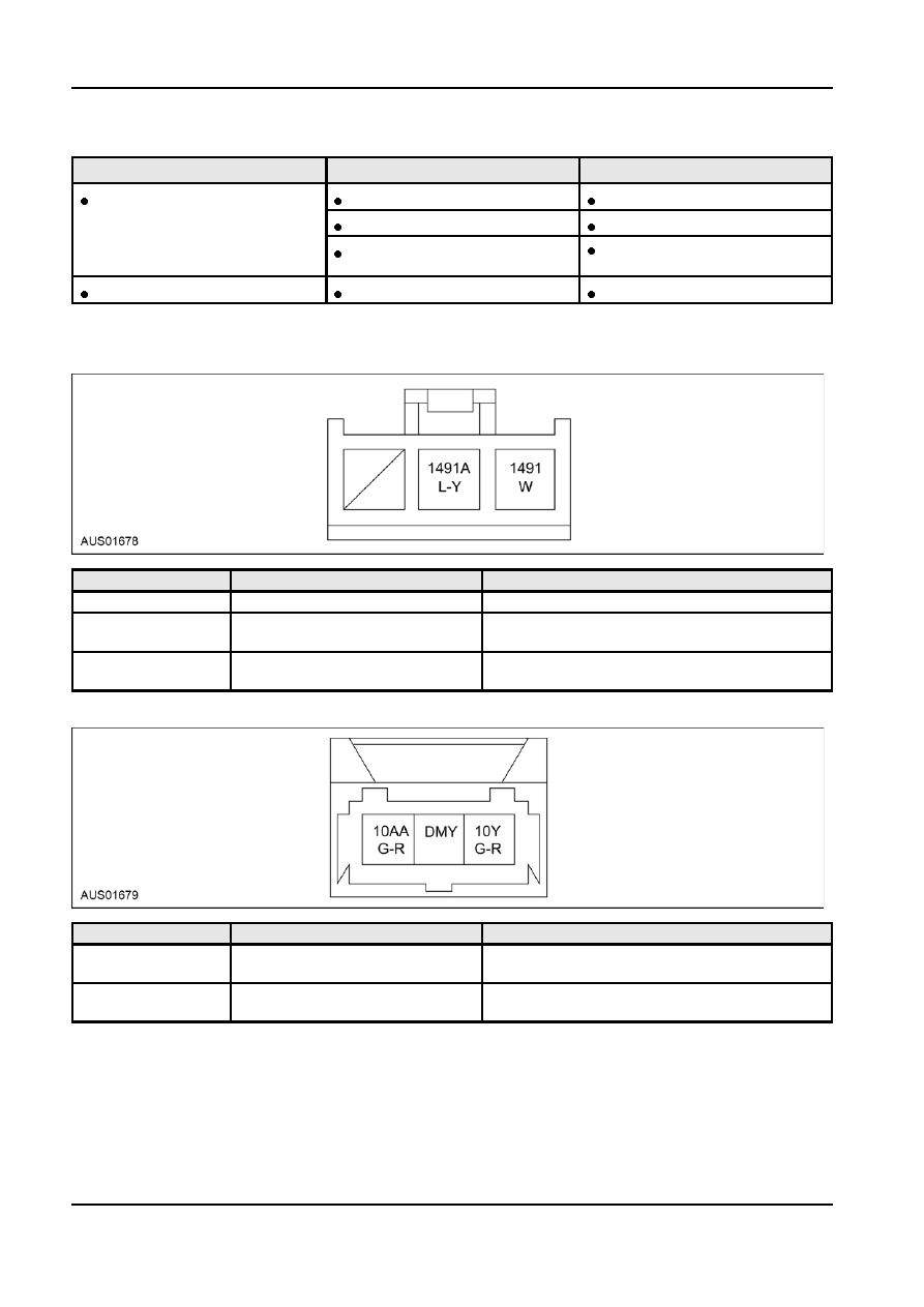
Connector Circuit Reference

CONNECTOR C - 378 PEDAL POSITION SENSOR (POTENTIOMETER)

Pin Number(s)

Circuit Designation/Description

Normal Condition/Measurement

1

BLANK

2

1491A (Blue / Yellow)

Resistance / Voltage

Pedal Position Sensor A

3

1491 (White)

Resistance / Voltage

Pedal Position Sensor B

CONNECTOR C - 191 BRAKE LAMP SWITCH

Pin Number(s)

Circuit Designation/Description

Normal Condition/Measurement

1

10AA (Green / Red)

Ohms - Continuity

Brake Switch High

(only with pedal depressed)

2

10Y (Green / Red)

Ohms - Continuity

Brake Switch Signal

(only with pedal depressed)

G22114 en

206-06-9 Hydraulic 

Brake 

Actuation 206-06-9

DIAGNOSIS AND TESTING (Continued)

CONNECTOR C - 379 PEDAL ADJUSTING MOTOR
NOTE: 
Ignition to be "ON" for Voltage Tests.

NOTE: Battery to be disconnected for resistance checks.

Pin Number(s)

Circuit Designation/Description

Normal Condition/Measurement

1

1489 (R), 1494 (L)

Voltage less than 2 Volts

2

1490 (W), 1495 (R)

Voltage less than 2 Volts

CONNECTOR C - 36 CRUISE CONTROL SWITCH (BRAKE PEDAL)

Pin Number(s)

Circuit Designation/Description

Normal Condition/Measurement

1

10AC (Green/Red)

Ohms - Continuity

Cruise Control - High

2

511 (Blue/Green)

Ohms - Continuity

Cruise Control - Signal

CONNECTOR C - 111 CRUISE CONTROL SWITCH (CLUTCH)

Pin Number(s)

Circuit Designation/Description

Normal Condition/Measurement

1

10AC (Green/Red)

Ohms - Continuity

Cruise Control - Signal

(Yes - nominal state)

2

57FH ((Blue)

Ohms - Continuity

Cruise Control - High

(Yes - nominal state)

G22114 en

206-06-10 Hydraulic 

Brake 

Actuation 206-06-10

DIAGNOSIS AND TESTING (Continued)

CONNECTOR C - 395 PEDAL BOX HARNESS
NOTE: 
Depending on the vehicle level some of the terminals listed below will be blank. High series connector

shown. Values given are with connector C-395 connected, ignition on and back probing the terminals.

Pin Number(s)

Circuit Designation/Description

Normal Condition/Measurement

1

10AB (Green/Red)

12 - 14 Volts

Brake and Cruise switch (High)

2

1489 (Red)

Using adjustment switch - Centre =0 Volts,

Pedal adjusting motor - A

Upwards = 12-14 Volts. Downwards = 0.1 Volt

3

1490 (White)

Using adjustment switch - Centre =0 Volts,

Pedal adjusting motor - B

Upwards = 0.1 Volt. Downwards = 12-14 Volts

4

57 H (Black) Clutch switch

N/A

5

511 (Blue/Green)

12-14 Volts (Brake pedal pushed - 0 Volts)

Cruise control deactivation switch -

signal

10Y (Green/Red)

0 Volts (Brake pedal pushed - 12-14 Volts)

Brake switch - signal

1491 (White)

N/A

Pedal position sensor - B

1491A (Blue/Yellow)

N/A

Pedal position sensor - A

BLANK

92 (Blue/Yellow)

N/A

Clutch switch - signal

Pinpoint Tests

PINPOINT TEST A : EXCESSIVE BRAKE PEDAL MOVEMENT AT PIVOT

Test Step

Result / Action to Take

A1

PEDAL MOVEMENT CHECK

Grasp the Brake pedal pad area with your hand.

Yes

Go to A2

Move the pedal from side to side to check for movement at the upper
pivot area.

No

Okay

Carry out check in the applied and not applied brake pedal position.

Is the pedal movement more than the maximum of 

± 3.5 mm?

G22114 en

206-06-11 Hydraulic 

Brake 

Actuation 206-06-11

DIAGNOSIS AND TESTING (Continued)

Test Step

Result / Action to Take

A2

PIVOT PIN HOUSING DAMAGE

Carry out this check the same as described in test step A 1.

Yes

Replace the pedal box assembly.

Using a Torch visually inspect for any cracks around the pivot pin

Refer to removal and installation instructions in

housing as the pedal is moved side to side and applied towards floor.

this chapter.

Were any cracks found?

No

Okay

PINPOINT TEST B : PEDAL FEEL INCORRECT

 CAUTION: Step B2, Remember to tighten the Booster retaining nuts to (22.5 +/- 3.4 NM) when the

test is completed.

Test Step

Result / Action to Take

B1

OBSTRUCTIONS AT PEDAL

Check for obstructions at and / under the brake pedal, such as a floor

Yes

mat or wiring harness fouling the upper mechanism.

Remove the obstruction and recheck

Did you find an obstruction?

No

Go to B2

B2

BRAKE PEDAL RETURN

Loosen the Four nuts used to retain the brake booster to the pedal

Yes

box.

Replace the pedal box assembly.
Refer to removal and installation instructions in

Remove the pin used to retain the booster rod to the brake pedal.

this chapter.

Detach the booster rod from the brake pedal.

No

Move the brake pedal up and down slowly, looking for evidence of

Go to the brake booster. Refer to removal and

binding.

installation instructions in this chapter

Did the brake pedal bind when moving up and down?

PINPOINT TEST C : STOP LAMP SWITCH

Test Step

Result / Action to Take

C1

STOP LAMP OPERATIONAL CHECK

Ignition ON.

Yes

Stop lamp circuit Okay

Apply brake pedal.

No

Do the rear Stop lamps illuminate?

Go to C2

C2

STOP LAMP CIRCUIT FUSE

Check the 15 Amp Fuse # 7.

Yes

Replace Fuse and recheck.

Was Fuse blown?

NOTE: If Fuse blows again, this could indicate
an electrical system fault.

No

Go to C3

G22114 en


Content   ..  70  71  72  73   ..