Ford Ranger EV. Electric Manual - part 9
 

  Index      Ford     Ford Ranger EV - Electric manual 1998 year


Search            


Content   ..  7  8  9  10   ..


Ford Ranger EV. Electric Manual - part 9


LESSON 1: VEHICLE OVERVIEW

1-33

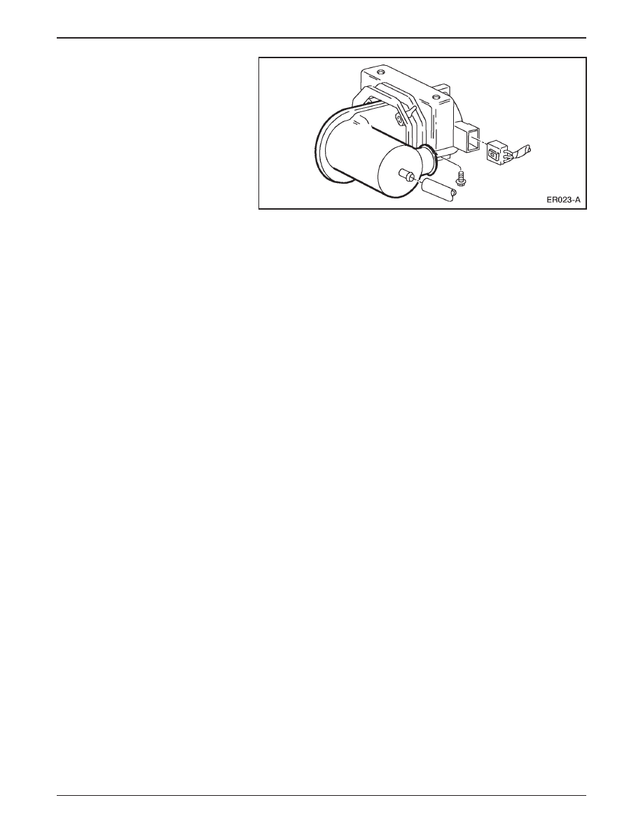
Motor Driven Vacuum Pump

A motor driven vacuum pump is mounted beneath the

battery charger.

The anti-lock braking system (ABS) is a 4-sensor 3-channel

system.

ABS components include:

– an electronic control unit (ECU).

– an Explorer hydraulic control unit (HCU).

– a Ranger mounting bracket.

The ABS system sends active line output to the TIM for use with

the regenerative braking system.

All of the electric components in the braking system operate off

low voltage circuits.

LESSON 1: VEHICLE OVERVIEW

1-34

Regenerative Braking System (RBS)

Regenerative Braking System (RBS)

In a conventional friction braking system, the kinetic energy of

deceleration is transformed into heat.

– This heat is dissipated into the surrounding air.

The function of the regenerative braking system (RBS) is to

recover some of this kinetic energy during deceleration and

improve overall vehicle efficiency.

Regenerative braking is accomplished by using vehicle

deceleration to drive the motor/transaxle.

– This causes the motor to act as a generator and convert vehicle

kinetic energy into electrical energy that is stored by the traction

battery.

ER024-A

Electrical
energy

Kinetic
energy

LESSON 1: VEHICLE OVERVIEW

1-35

The accelerator pedal and the brake pedal are inputs of the RBS.

RBS supplements the hydraulic braking system.

The RBS operates when the vehicle is moving either forward or

backward.

It is possible for RBS motor torque to cause rear wheel slip in

certain circumstances.

– To prevent excessive wheel slip, the RBS is designed to work

with the anti-lock brake system (ABS) module.

– Whenever an ABS event occurs, the ABS module signals the

TIM, which reduces regenerative braking.

– The RBS is returned to its prior state after the ABS event.

NOTE: The IAA triggers the red BRAKE warning lamp in the

instrument cluster if an RBS fault occurs. The vehicle can be safely

operated without RBS.

LESSON 1: VEHICLE OVERVIEW

1-36

ELECTRONIC THROTTLE CONTROL

ER025-A

1

2

Electronic Throttle Control Components

Item

Description

1

Accelerator Position Sensor (APS)

2

Accelerator Pedal Assembly

Electronic throttle control is in use on vehicles other than

Electric Ranger.

On the Electric Ranger, electronic throttle control replaces the

cable between the accelerator pedal and the powertrain.

Instead of a mechanical request for power, electronic throttle

control uses electrical signals.

The sensing component of electronic throttle control is an

accelerator position sensor (APS) mounted to the accelerator

pedal assembly.

– Three potentiometers in the APS sense the position of the

accelerator pedal.

– The APS sends signals to the TIM, which commands the

motor/transaxle to respond accordingly.


Content   ..  7  8  9  10   ..