Ford Focus RS (2011 year). Instruction - part 102


  Index      Ford     Ford Focus RS - service repair manual (2011 year) in english


Search            


Content   ..  100  101  102  103   ..


Ford Focus RS (2011 year). Instruction - part 102


Scrapped Vehicle Undeployed Air Bag Disposal

Special Tool(s)

Test and Deployment Lead,
Air Bag/Pyrotechnic Safety
Belt
418-S055 (40-007A)

IA40007

General Equipment

12 volt battery

All vehicles

WARNINGS:

To minimize the possibility of injury in the
event of premature deployment, always
carry a live air bag module with the bag
and trim cover pointed away from the body.
Failure to follow this instruction may result
in personal injury.

To minimize the possibility of premature
deployment, live air bag modules must
only be placed on work benches which
have been ground bonded. Failure to follow
this instruction may result in personal
injury.

1. Disconnect the battery ground cable. For

2. Remove the air bag module(s) to be

deployed. For additional information, refer
to the relevant procedure(s) in this section.

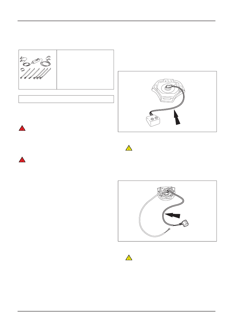
Single stage air bag modules

3. Connect the test lead to the air bag module

and the adapter (driver air bag module
shown).

TIE0022048

Two stage air bag modules

4.

CAUTION: Do not connect both test leads

to the adapter. Both air bag module inflators
must be deployed separately.

Connect two test leads to the air bag module
and the other end of one of the test leads to
the adapter (driver air bag module shown).

TIE0022046

All air bag modules

5.

CAUTION: To protect the test lead

electrical connector(s) from damage during
deployment, raise the air bag module off the
ground on two wooden blocks.

G18616en

501-20B-

120

Supplemental Restraint System

501-20B-

120

GENERAL PROCEDURES

Place the air bag module inside a suitable
rigid wire cage with the air bag module cover
uppermost.

TIE0004023

6. Connect the deployment lead to the adapter.

DTL4003008

7.

WARNING: Before proceeding make sure

that all personnel in the vicinity are aware
that a loud noise (bang) is about to occur.
Do not let anybody approach closer than six
meters. Failure to follow this instruction may
result in personal injury.

Move as far away as possible from the air
bag module and connect the deployment
lead to the battery.

DTL4003009

8. CAUTIONS:

The air bag module should not be

handled immediately following deployment
as the air bag module will be very hot.

After deployment, the air bag module

surface may contain deposits of sodium
hydroxide, a product of the gas generate
combustion, that is irritating to the skin. Use
protective gloves when handling any
deployed air bag module.

Depress both switches to deploy the air bag.

DTL4003010

Two stage air bag modules

9. Connect the second test lead to the adapter.

TIE0022047

10.

WARNING: Before proceeding make

sure that all personnel in the vicinity are
aware that a loud noise (bang) is about to
occur. Do not let anybody approach closer
than six meters. Failure to follow this
instruction may result in personal injury.

CAUTIONS:

The air bag module should not be handled
immediately following deployment as the
air bag module will be very hot.

G18616en

501-20B-

121

Supplemental Restraint System

501-20B-

121

GENERAL PROCEDURES

After deployment, the air bag module
surface may contain deposits of sodium
hydroxide, a product of the gas generate
combustion, that is irritating to the skin.
Use protective gloves when handling any
deployed air bag module.

Depress both switches to deploy the air bag.

DTL4003010

All air bag modules

11. Deployed air bag module(s) should be

sealed in a suitable bag and then disposed
of in accordance with local contaminated
waste regulations.

G18616en

501-20B-

122

Supplemental Restraint System

501-20B-

122

GENERAL PROCEDURES

Unserviceable Air Bag Disposal

1. WARNINGS:

To minimize the possibility of injury in

the event of premature deployment, always
carry a live air bag module with the bag and
trim cover pointed away from the body.
Failure to follow this instruction may result
in personal injury.

To prevent premature deployment, live

air bag modules must only be placed on work
benches which have been ground bonded.
Failure to follow this instruction may result
in personal injury.

NOTE: All unserviceable air bag modules have
been placed on the Mandatory Return List. All
discolored or damaged air bag modules should be
treated the same as any unserviceable live air bag
module being returned.

Remove the unserviceable air bag module.
For additional information, refer to the
relevant procedure in this section.

2.

WARNING: Under no circumstances is

an unserviceable air bag module(s) to be
returned through the local mailing system.
Failure to follow this instruction may result
in personal injury.

Seal the unserviceable air bag module(s) in
the packaging from the new air bag
module(s) and address to the appropriate
manufacturer. The package should then be
forwarded to the Exchange Plan Center (as
appointed through the national sales
company) who will arrange forwarding to the
manufacturer.

3. NOTE: Autoliv air bag modules and seat belt

pretensioners.

Autoliv Gmbh, Theodor Heuss Strasse 2,
85221, Dachau, Germany.

4. NOTE: TRW air bag modules.

TRW Occupant Restraint Systems, FAO Rene
Getto, Industriestr 20, 73551, Aldorf,
Germany.

5. NOTE: TRW seat belt pretensioners.

TRW Occupant Restraint Systems, FAO
Helmut Goss, Industriestr 20, 73551, Aldorf,
Germany.

6. NOTE: Takata Petri air bag modules.

Takata Petri AG, Grossostheimer Strasse
223, D-63741 Aschaffenburg, (Supplier Code
P790M) Germany.

G18617en

501-20B-

123

Supplemental Restraint System

501-20B-

123

GENERAL PROCEDURES

Crash Sensor

WARNINGS:

To avoid accidental deployment, the
restraints control module backup power
supply must be depleted. Wait at least one
minute after disconnecting the battery
ground cable(s) before commencing any
repair or adjustment to the supplemental
restraint system (SRS), or any
component(s) adjacent to the SRS sensors.
Failure to follow these instructions may
result in personal injury.

To minimize the possibility of premature
deployment, do not use radio key code
savers when working on the supplemental

restraint system. Failure to follow this
instruction may result in personal injury.

Never probe the electrical connectors of
air bag modules or any other supplemental
restraint system component. Failure to
follow this instruction may result in
personal injury.

1. Disconnect the battery ground cable.

Mounting and Cables, General Procedures).

2. Remove the components in the order

indicated in the following illustration(s) and
table(s).

TIE39512

4

1

3

8 Nm

2

Description

Item

Radiator air deflector

1

Crash sensor retaining bolt

2

Crash sensor electrical connector

3

Crash sensor

4

All vehicles

3. To install, reverse the removal procedure.

Vehicles with global closing

4. Initialize the door window motors.

G296345en

501-20B-

124

Supplemental Restraint System

501-20B-

124

REMOVAL AND INSTALLATION

Disconnect and Connect

(414-01 Battery,

For additional information, refer to:

Battery

Window Motor Initialization

(501-11 Glass,

See Installation Detail

For additional information, refer to:

Door

Frames and Mechanisms, General

Procedures).

Installation Details

Item 4

Crash sensor

WARNING: Make sure the crash sensor
locating tang is correctly located in the
grille opening panel. Failure to follow this
instruction may result in personal injury.

G296345en

501-20B-

125

Supplemental Restraint System

501-20B-

125

REMOVAL AND INSTALLATION

Side Impact Sensor

WARNINGS:

To avoid accidental deployment, the
restraints control module backup power
supply must be depleted. Wait at least one
minute after disconnecting the battery
ground cable(s) before commencing any
repair or adjustment to the supplemental
restraint system (SRS), or any
component(s) adjacent to the SRS sensors.
Failure to follow these instructions may
result in personal injury.

To minimize the possibility of premature
deployment, do not use radio key code
savers when working on the supplemental
restraint system. Failure to follow this
instruction may result in personal injury.

Never probe the electrical connectors of
air bag modules or any other supplemental

restraint system component. Failure to
follow this instruction may result in
personal injury.

1. Disconnect the battery ground cable.

Mounting and Cables, General Procedures).

2. Remove the B-pillar trim panel. For additional

information, refer to: (501-05 Interior Trim
and Ornamentation)

Installation),

and Installation).

3. Remove the components in the order

table(s).

TIE39499

3

1

9 Nm

2

Description

Item

Side impact sensor electrical connector

1

Side impact sensor retaining bolt

2

Side impact sensor

3

All vehicles

WARNING: Make sure the side impact
sensor locating tangs are correctly located
into the floor pan. Failure to follow this
instruction may result in personal injury.

G296346en

501-20B-

126

Supplemental Restraint System

501-20B-

126

REMOVAL AND INSTALLATION

For additional information, refer to:

Battery

B-Pillar Trim Panel - 3-Door

(Removal and

Disconnect and Connect

(414-01 Battery,

indicated in the following illustration(s) and

B-Pillar Trim Panel - 4-Door/5-Door

(Removal

4. To install, reverse the removal procedure.

Vehicles with global closing

5. Initialize the door window motors.

For additional information, refer to:

Door

Frames and Mechanisms, General
Procedures).

G296346en

501-20B-

127

Supplemental Restraint System

501-20B-

127

REMOVAL AND INSTALLATION

Window Motor Initialization

(501-11 Glass,


Content   ..  100  101  102  103   ..