Ford Focus RS (2011 year). Instruction - part 96
DETAILS/RESULTS/ACTIONS
TEST CONDITIONS
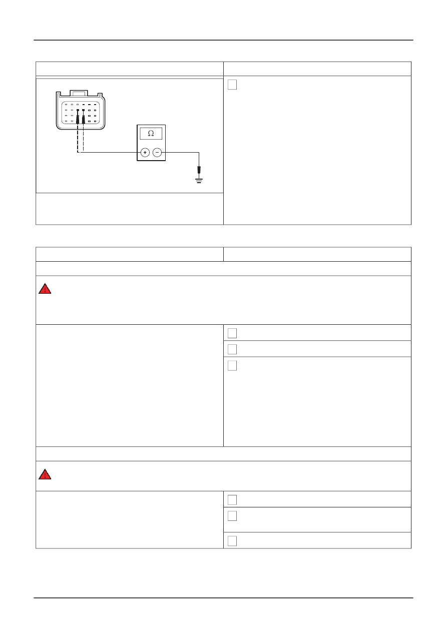
4 Measure the resistance between the:
• RCM C426 pin 9, circuit 15S-JA31 (GN/WH),
harness side and ground.
• RCM C426 pin 10, circuit 91S-JA31 (BK/WH),
harness side and ground.
VUE0029822
• Are the resistances greater than 10,000 ohms?
ൺ
Yes
REPEAT the self-test, CLEAR the DTCs.
REACTIVATE the system.
ൺ
No
REPAIR circuit 15S-JA31 (GN/WH) or circuit
91S-JA31 (BK/WH). REPEAT the self-test,
CLEAR the DTCs. REACTIVATE the system.
PINPOINT TEST AL : DTC B1992: DRIVER SIDE AIR BAG CIRCUIT SHORT TO BATTERY
DETAILS/RESULTS/ACTIONS
TEST CONDITIONS
AL1: CHECK THE DRIVER SIDE AIR BAG CIRCUIT
WARNING: To avoid accidental deployment, the RCM backup power supply must be depleted.
Wait at least one minute after disconnecting the battery ground cable(s) before commencing
any repair or adjustment to the SRS, or any component(s) adjacent to the SRS sensors.
Failure to follow these instructions may result in personal injury.
1 Deactivate the SRS.
2 Ignition switch in position II.
3 Carry out the self-test with the simulators
installed.
• Does the system prove out correctly?
ൺ
Yes
GO to AL2.
ൺ
No
GO to AL3.
AL2: CHECK THE DRIVER SIDE AIR BAG MODULE
WARNING: Do not proceed with this test unless using the Ford approved diagnostic tool.
Failure to follow this instruction may result in personal injury.
1 Ignition switch in position 0.
2 Select DMM specific on the Ford approved
diagnostic tool.
3 Disconnect RCM C429.
G401865en
501-20B-
72
Supplemental Restraint System
501-20B-
72
DIAGNOSIS AND TESTING